| Technical Specification and Scope of Supply
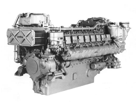
MTU 16V 165 TE5 Diesel Engine (MTU 16V396)
1580 kW•1800 rpm
General Data
Overload power: 1740KW
The engine power represents the net brake power according to ISO 3046 at the PTO flange.
Application MTU application group 3A:
Overload: 10%
Reference Conditions
♦ Intake air temperature 25°C
♦ Charge air coolant temperature 50°C
♦ Barometric pressure 1000 mbar
♦ Intake air depression 20 mbar
♦ Exhaust back pressure 30 mbar
♦ Altitude above sea level 100 m
Note: When environment condition differs, correct the power according to the relevant technical document.
Basic Design
♦ 16 cylinders
♦ 90°V cylinder arrangement
♦ Four-stroke diesel
♦ Liquid cooling
♦ Direct fuel injection
♦ Exhaust turbo-charging and charge-air cooling
♦ Wet, replaceable cylinder liners
♦ Shunt coolant circuit
♦ Piston cooling
♦ 2 inlet, 2 exhaust valves per cylinder
♦ Triple-walled, liquid-cooled exhaust lines
♦ Bore 165 mm
♦ Stroke 185 mm
♦ Single Cylinder displacement 3.96 L
♦ Total displacement 63.3 L
♦ Compression ratio 13.5
♦ Direction of rotation ccw
(facing driving end)
♦ Smoke index 1.0SZ(Bosch)
Physical characteristic
Associated standard load profile:
100%load 5%time
50% load 80% time
<15% load 15% time
♦ Engine dry weight (with engine-mounted standard oil accessories incl. coupling) 5510+5%kg
♦ Dimention(length×width×high) :3060×1530×1750mm
ENGINE DATA 16V165TE5(MTU 16V396)
|
Power related data (power ratings are net brake power to ISO 3046)
Speed
Mean piston speed
Continuous power to ISO 3046 (10% overload cap. Design power to DIN6280,ISO 8528) CP
Fuel stop power to ISO 3046 FSP
MEP CP
MEP FSP |
rpm
m/s
kW
kW
bar
bar |
1800
11.1
1580
1740
16.8
18.5 |
|
|
|
Specific fuel consumption (+5%;DIN 51601;42.8MJ/kg)
- 100% load CP
- 75% load CP
- 50% load CP
- 25% load CP
- FSP
- neutral gear
Lube oil consumption after 100h operation
|
g/kW·h
g/kW·h
g/kW·h
g/kW·h
g/kW·h
kg/h |
210
219
224
244
211
19
Average 0.5% of spec. fuel consumption |
|
|
|
Oil and Coolant Capacity
Engine lube oil (standard oil system)
Total initial filling
Oil dipstick, min./max
Oil change quantity
Engine coolant, total
On-engine fuel capacity
|
lit.
lit.
lit.
lit.
lit. |
230
90/180
180
230
5 |
|
|
|
Heat Dissipation
Heat dissipated by engine coolant
Heat dissipated by return flow fuel
Radiation and convection heat, engine
|
kW
kW
kW |
1305
6
40 |
|
|
|
Coolant circuit
Coolant temperature (after engine to cooling equipment)
Coolant temperature after engine from/to
Coolant temperature after engine. alarm
Coolant temperature after engine. shutdown
|
°C
°C
°C
°C |
85
78/85
87+2
90+2 |
|
|
|
Fuel System
Fuel pressure at supply connection on engine,
min./max, permissible
Fuel flow rate to engine, max.
Fuel return flow from engine, max.
Fuel pressure at return connection on engine, max. permissible
Fuel temperature difference before and after engine
|
bar
lit./min
lit/min
bar
°C |
-0.3/+0.5
18
14
1.5
11 |
|
|
|
Combustion-air System
Combustion-air flow rate CP
Charge air pressure before cylinder
Intake air depression, design/max. permissible
|
m3/s
bar
mbar |
2.50
3.0
20/35 |
|
|
|
Lube oil system
Lube oil operation temperature before engine from/to
Lube oil operation temperature after engine from/to
Lube oil temperature before engine, alarm
Lube oil temperature before engine, shutdown
Lube oil operation pressure before engine from/to
Lube oil pressure before engine, alarm
Lube oil pressure before engine, shutdown
|
°C
°C
°C
°C
bar
bar
bar |
85/90
95/100
105
110
5.5/6.0
4.0
3. |
|
|
|
Exhaust System
Exhaust gas flow rate CP
Exhaust gas temperature after turbocharger CP
Exhaust back pressure, design/max, permissible
|
m3/s
°C
mbar |
7.6
600
30/50 |
|
|
|
Starting system
Starting (air in cylinder)
- Starting air pressure (min/max value)
- Starting air pressure (min/max limit value)
- Air consumption/start sequence
- Start during (engine preheated)
- Start air storage (max.40 bar)
- Start air storage (max. 30bar)
Starting (electric)
- Starter rated power
- Starter rated voltage
- Starter power consumption max.
- Starter power consumption at firing speed
- Recommended battery capacity
|
bar
bar
m3
s
lit.
lit
kW
V
A
A
Ah/20h |
20/40
16/40
0.6
2
320
400
15
24
2500
850
270 |
|
|
SCOPE OF SUPPLY
A. Engine with Standard Equipment
Liquid-cooled four-stroke diesel engine, anti-clockwise direction of rotation (viewed on driving end), with direct fuel injection, controlled exhaust gas turbo-charging and charge-air cooling; crankcase with oil pan and bolted-on flywheel housing (SAE 0-flange); individual, four-valve cylinder heads with "Rotocap" valve rotators; fuel delivery pump; fuel duplex filter with diverter valve; Bosch block-type injection pump with emergency shutdown lever and cylinder-cutout system; lube oil pump; lube oil heat exchanger; lube oil multi-stage filter with in-line back-up filter, coolant circulation pump; coolant thermostat; gear train for valve gear and auxiliary PTO; vibration damper (subject to torsional vibration calculation); normal and safety engine shutdown via emergency air shut-off flaps; all necessary on-engine air, exhaust, coolant, fuel and oil pipework.
1. Pressure charging system
- 2 turbochargers.
- 1 intercooler(internal cooling).
2. Fuel system
- Fuel delivery pump with hand priming pump.
- Block-type injection pump with emergency shutdown lever. Fuel rack indicator.
3. Engine governor
- governor with two stage start fuel limitation.
4. Lube oil system
-Oil pump. Oil heat exchanger. Oil filter. Oil filling neck & dipstick. Crankcase breather. Metering pump for valve seat lubrication.
5. Cooling system
-coolant pump. coolant thermostat.
6. Shutdown equipment
- Normal shutdown via governor actuator/injection pump (24 VDC, governor actuator).
- Safety shutdown via emergency air shutoff flaps, by stoppage of combustion air supply (24 VDC solenoid)
B. Engine accessories
1. Air-in-cylinder starting system
- compressed Air starting system with air distributor &starting valve(max. 40bar)
- flameproof hose line DN20.
-24VDC starting valve with emergency control lever.
Note: compressor, air tank & connecting parts supplied by others.
2. Electric starter system (24VDC, 15kW)
3. Fuel system
- hose line .
- High pressure fuel pipe
- flameproof hose line DN6.
4. Lube oil system
- 2 centrifugal oil filters used for extension of oil replenishment(optional).
5. Combustion Air System
- Set of air inlet connecter, mounted on inlet elbow of turbcharger.
6. Exhaust System
- companion flange for resilient connection of the exhaust system to both turbochargers for vertical exhaust connection.
7. Cooling System
- Coolant-to-raw water plate-core heat exchanger including coolant expansion tank with breather valve(optional).
8. Engine Mounting
- 4 pieces resilient engine mount.
C. Control and Monitoring System
1. Engine speed adjustment
-speed adjustment by set of 24VDC electric remote control equipment.
2. Sensors
- engine speed transmitters (double system) .
- temperature transmitters (PT1000), for lube oil/engine coolant/intake charge air
- 2 NiCrNi thermocouples for exhaust temperature after turbocharger.
- Level monitor for low engine coolant level.
- Limit switch for emergency air shut-off flap position display.
- Pressure transmitters (4-20 mA), for engine lube oil, coolant, charge air and fuel.
3. Measuring block
- for combination of all pressure measuring points including connecting lines.
4. Wiring
- On-engine wiring, including resiliently mounted terminal box with plug connector.
5. Local operating panel
Local operating panel LOP, in sheet metal housing, ready for installation with plug connector, and the following equipment:
Microprocessor controlled monitoring and control system, with:
-control logic for engine start / stop / emergency stop, with firing speed acquisition(start repeat protection and alarm suppression with engine stooped) and overspeed acquisition.
-Measuring and monitoring unit for processing binary and analogue input signal,with output for alarm logic(pressure measuring channel, engine speed corrected) and outputs for display units
-Alarm logic, processing of "lamp test" and " signals(to switch off horn and change signal lamps from flashing to continuous light mode).
-Auxiliary/control relay for engine start / stop / emergency stop and monitoring on/off
-circuit protection devices
-Electric display units for: engine speed/lube oil pressure/coolant temperature/exhaust temperature A and B/operating hours
- Warning lamps for: lube oil pressure/ lube oil pressure(shutdown)/coolant temperature/ coolant temperature(shutdoen)/engine overspeed(shutdown)/ exhaust temperature A and B/emergency air shut off flaps closed/sensor malfunction in alarm system/ sensor malfunction in safety system/alarm system failure/ safety system failure
- Signal lamps for engine running
- Pushbuttons for: ready for operation/ ngine start / stop / emergency stop,/alarm acknowledgement/alarm memory reset
- Changeover switch for "local/remote control"
Technical specification for Diesel Genset (16V396)
| Rated Power(continuous power ICFN) |
1310KW |
| Rated voltage |
690V |
| Rated frequency |
60Hz |
| cos |
0.8(lagging) |
| Protection class |
IP23 |
| Dimension (LxWxH) |
5000X1540X1750mm |
| Weight |
12500Kg | |
