|
Please Read on as following, also you can view the flow-process diagram at the end of this article.
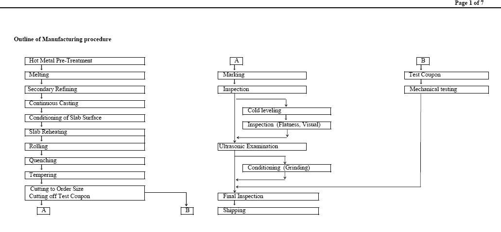
Outline of Manufacturing procedure
Page 1
Hot Metal Pre-Treatment A B
Melting  arking Test Coupon
Secondary Refining  nspection  echanical testing
Continuous Casting
 old leveling
Conditioning of Slab Surface
 nspection (Flatness, Visual) you can view the flow-process diagram at the end of this article.
Slab Reheating
Rolling Ultrasonic Examination
Quenching
 onditioning (Grinding)
Tempering
 utting to Order Size
Cutting off Test Coupon  inal Inspection
A B  hipping
Page 2 you can view the flow-process diagram at the end of this article.
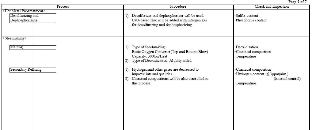
Process Procedure Check and Inspection
<Hot Metal Pre-treatment>
Desulfurizing and 1) Desulfurizer and dephosphorizer will be used. ・Sulfur content
Dephosphorizing CaO-based flux will be added with nitrogen gas ・Phosphorus content
for desulfurizing and dephosphorizing.
<Steelmaking>
Melting 1) Type of Steelmaking: ・Deoxidization
Basic Oxygen Converter(Top and Bottom Blow) ・Chemical composition
Capacity: 300ton/Heat ・Temperature
2) Type of Deoxidization: Al fully killed
Secondary Refining 1) Hydrogen and other gases are decreased to ・Chemical composition
improve internal qualities. ・Hydrogen content:�?ppm(aim.)
2) Chemical compositions will be also controlled in (Internal control)
this process. ・Temperature
Page 3 you can view the flow-process diagram at the end of this article.
Process Procedure Check and Inspection
<Steelmaking>
1) A sample of Ladle analysis is taken in this process. ・Chemical composition
Tundish Frequency: Once per heat
Sampling position : Middle of heat
Tundish capacity : max. 60ton
Table1.Chemical composition (mass %)
Ladle Analysis
Spec. Remarks
C 0.16 max.
Si 0.15-0.50
Mn 0.70-1.60 t �?0mm
1.00-1.60 t>40mm
P 0.035 max.
S 0.035 max.
Cu 0.35 max.
Ni 0.25 max.
Cr 0.25 max.
Mo 0.08 max.
V 0.10 max.
Nb 0.02 max.
Ti 0.03 max.
T.Al 0.020 min.
Cu+Ni+Cr+Mo 1.00 max.
Cr+Mo 0.32 max.
Nb+V 0.10 max.
Ceq 0.45 max.
Pcm 0.25 max.
Ceq = C+Mn/6+(Cr+Mo+V)/5+(Ni+Cu)/15
Pcm=C+Si/30 + Mn/20 + Cu/20 + Ni/60 +Cr/20 + Mo/15 + V/10 + 5B
Elements
Page 4 you can view the flow-process diagram at the end of this article.
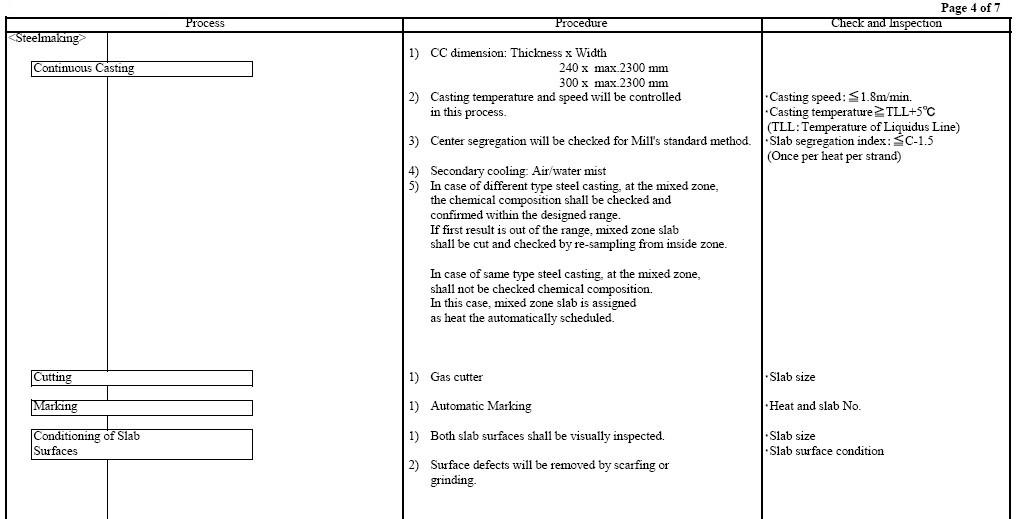
Process Procedure Check and Inspection
<Steelmaking>
1) CC dimension: Thickness x Width
Continuous Casting 240 x max.2300 mm
300 x max.2300 mm
2) Casting temperature and speed will be controlled ・Casting speed:�?.8m/min.
in this process. ・Casting temperature≧TLL+5°C
(TLL:Temperature of Liquidus Line)
3) Center segregation will be checked for Mill's standard method. ・Slab segregation index:≦C-1.5
(Once per heat per strand)
4) Secondary cooling: Air/water mist
5) In case of different type steel casting, at the mixed zone,
the chemical composition shall be checked and
confirmed within the designed range.
If first result is out of the range, mixed zone slab
shall be cut and checked by re-sampling from inside zone.
In case of same type steel casting, at the mixed zone,
shall not be checked chemical composition.
In this case, mixed zone slab is assigned
as heat the automatically scheduled.
Cutting 1) Gas cutter ・Slab size
Marking 1) Automatic Marking ・Heat and slab No.
Conditioning of Slab 1) Both slab surfaces shall be visually inspected. ・Slab size
Surfaces ・Slab surface condition
2) Surface defects will be removed by scarfing or
grinding
Page 5 you can view the flow-process diagram at the end of this article.
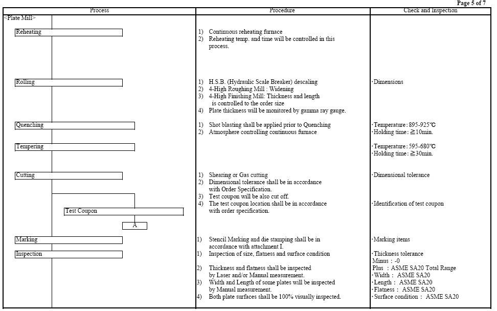
Process Procedure Check and Inspection
<Plate Mill>
Reheating 1) Continuous reheating furnace
2) Reheating temp. and time will be controlled in this
process.
Rolling 1) H.S.B. (Hydraulic Scale Breaker) descaling ・Dimensions
2) 4-High Roughing Mill : Widening
3) 4-High Finishing Mill: Thickness and length
is controlled to the order size
4) Plate thickness will be monitored by gamma ray gauge.
Quenching 1) Shot blasting shall be applied prior to Quenching ・Temperature:895-925°C
2) Atmosphere controlling continuous furnace ・Holding time:�?0min.
Tempering ・Temperature:595-680°C
・Holding time:�?0min.
Cutting 1) Shearing or Gas cutting ・Dimensional tolerance
2) Dimensional tolerance shall be in accordance
with Order Specification.
3) Test coupon will be also cut off.
4) The test coupon location shall be in accordance ・Identification of test coupon
Test Coupon with order specification.
A
Marking 1) Stencil Marking and die stamping shall be in ・Marking items
accordance with attachment I.
Inspection 1) Inspection of size, flatness and surface condition ・Thickness tolerance
Minus : -0
2) Thickness and flatness shall be inspected Plus : ASME SA20 Total Range
by Laser and/or Manual measurement. ・Width: ASME SA20
3) Width and Length of some plates will be inspected ・Length: ASME SA20
by Manual measurement. ・Flatness: ASME SA20
4) Both plate surfaces shall be 100% visually inspected. ・Surface condition: ASME SA20
Page 6 you can view the flow-process diagram at the end of this article.
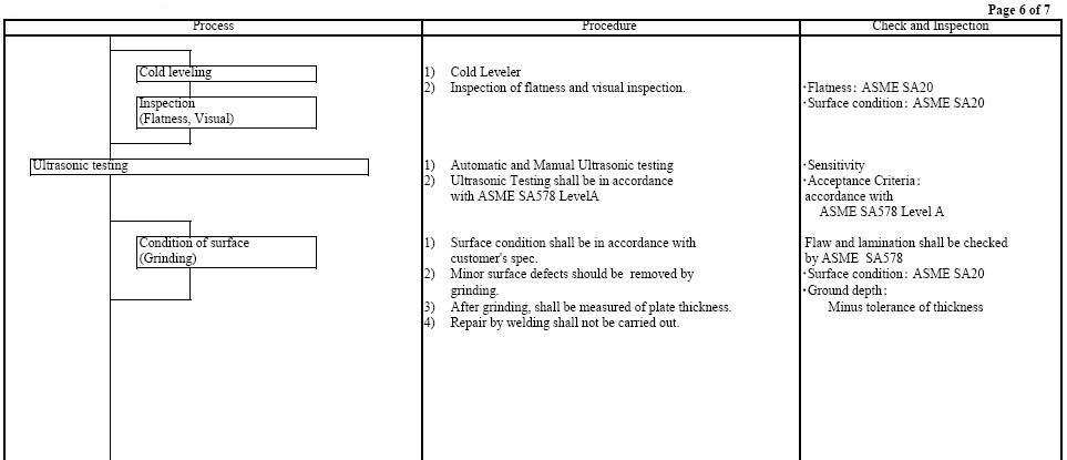
Process Procedure Check and Inspection
Cold leveling 1) Cold Leveler
2) Inspection of flatness and visual inspection. ・Flatness: ASME SA20
Inspection ・Surface condition: ASME SA20
(Flatness, Visual)
Ultrasonic testing 1) Automatic and Manual Ultrasonic testing ・Sensitivity
2) Ultrasonic Testing shall be in accordance ・Acceptance Criteria:
with ASME SA578 LevelA accordance with
 �ASME SA578 Level A
Condition of surface 1) Surface condition shall be in accordance with Flaw and lamination shall be checked
(Grinding) customer's spec. by ASME SA578
2) Minor surface defects should be removed by ・Surface condition: ASME SA20
grinding. ・Ground depth:
3) After grinding, shall be measured of plate thickness. Minus tolerance of thickness
4) Repair by welding shall not be carried out.
Page 7 you can view the flow-process diagram at the end of this article.
Process Procedure Check and Inspection
3) After grinding, shall be measured of plate thickness.
A
Mechanical testing 1) Mechanical test and product analysis
Location:a corner of the plate
PWHT 1) Atmosphere controlling electric or gas burner batch furnace ・Holding temp.:595°C±10°C 1cycle
・Holding time:minimum 8hrs
・Heating rate:max.100°C/Hr(Above 300°C)
・Cooling rate:max.126°C/Hr(Above 300°C)
Items Frequency Location Specimen Position/Direction Specification
Yield strength Each plate as heat-treated, a corner of the plate ASME SA370 ASME SA370 415 min. �?
(0.2%Offset/MPa) Both ends (after PWHT)
Tensile strength (MPa) 550-690
Elongation (%) 22 min.
Charpy impact test Each plate as heat-treated, ASME SA370 1/4t Longitudinal 27/20 min. �?
at -20°C(J) One end (after PWHT) (Average/Individual)
Product Analysis Once per each heat - - Imformation only
Final inspection
Inspection Certificate 1) Certificate shall be issued by computer system.
2) Result of ultrasonic examinations shall be reported
Shipping in the certificate as following
"ULTRASONIC EXAMINATION: ACCEPTABLE"
 /DIV>
Page 8 you can view the flow-process diagram at the end of this article.
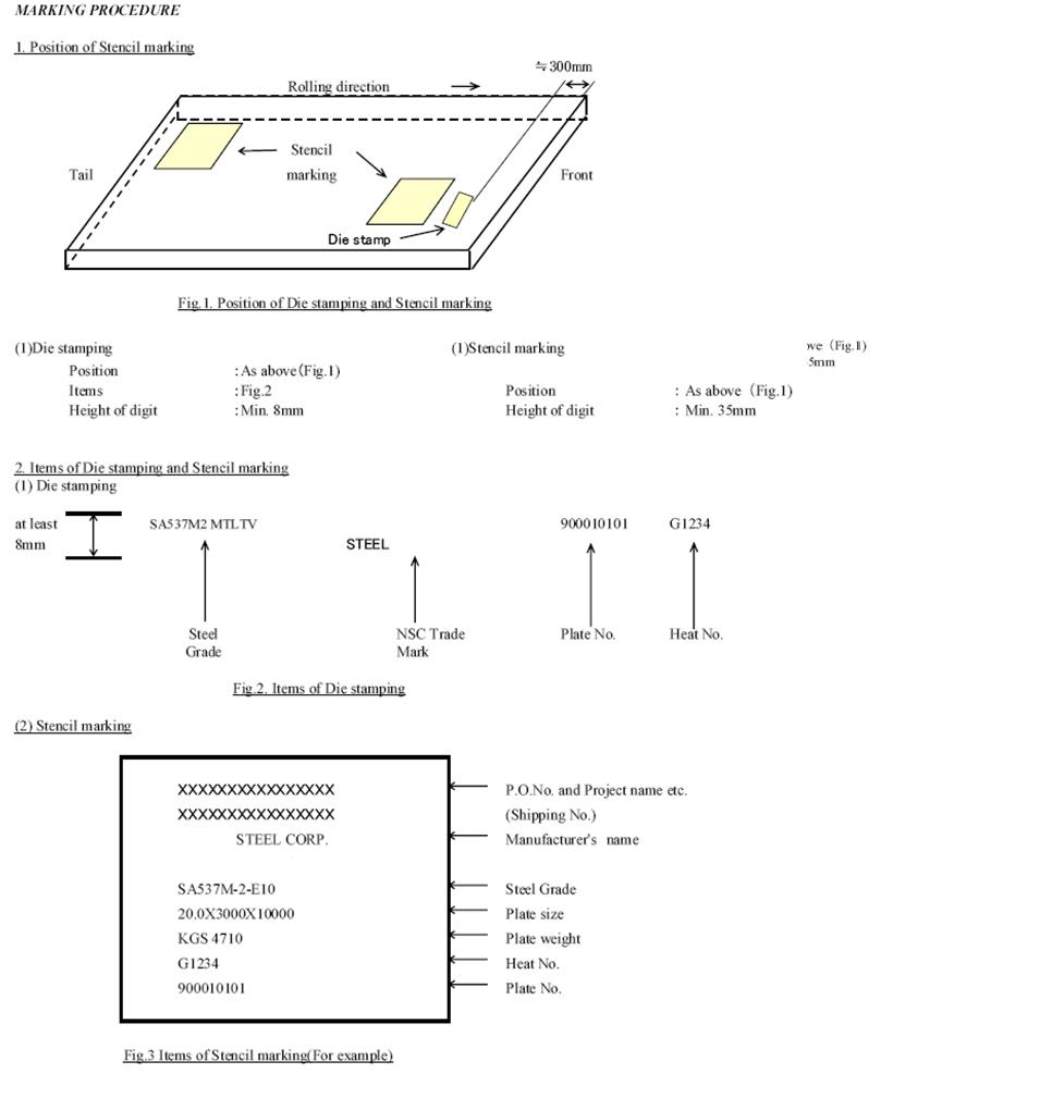
MARKING PROCEDURE
1. Position of Stencil marking
�?00mm
Rolling direction
Stencil
Tail marking Front
Die stamp
Fig.1. Position of Die stamping and Stencil marking
(1)Die stamping (1)Stencil marking
Position :As above(Fig.1)
Items :Fig.2 Position :As above(Fig.1)
Height of digit :Min. 8mm Height of digit :Min. 35mm
2. Items of Die stamping and Stencil marking
(1) Die stamping
at least SA537M2 MTLTV n 900010101 G1234
8mm STEEL
Steel NSC Trade Plate No. Heat No.
Grade Mark
Fig.2. Items of Die stamping
(2) Stencil marking
XXXXXXXXXX P.O.No. and Project name etc.
XXXXXXXXXX (Shipping No.)
XXX STEEL CORP. Manufacturer's ame
SA537M-2-E10 Steel Grade
20.0X3000X10000 Plate size
KGS 4710 Plate weight
G1234 Heat No.
900010101 Plate No.
Fig.3 Items of Stencil marking(For example)
|