|
Technical specification of Natural
gas generator set
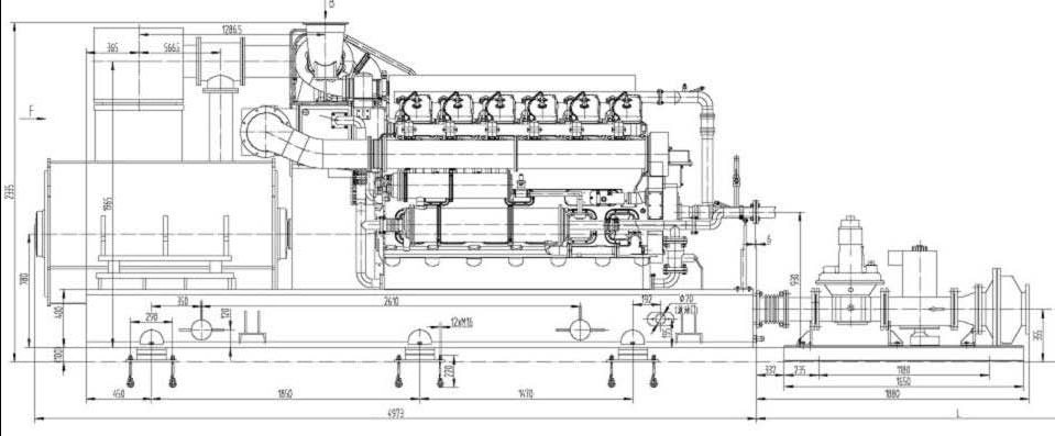
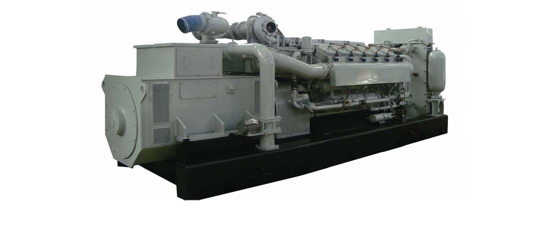
for 25mw by 40x700Kw MODEL:700GFZŌĆÉPwTŌĆÉTEM2
Natural gas generator set
Leda Greenpower Beijing
Feb. 2012
A. The Leader manufacturer of gas/diesel generator set in China
B.A. Technical specification of gas generator set
|
Mode |
700GFZŌĆÉPwTŌĆÉTEM2 |
|
Generator model |
1FC6 458-6 |
|
Rated power (kW) |
700 |
|
Rated current (A) |
1263 |
|
Rated voltage (V) |
400 |
|
COS╬” Rated power factor, COS╬” |
0.8(lagging) |
|
Frequency(Hz) |
50 |
|
Starting method |
24V DC motor starting |
|
Voltage regulation |
Automatic voltage regulation |
|
Governing Method |
Electronic Governing |
|
Exciting method |
Brushless |
|
Phase and wiring |
ThreeŌĆÉphase, fourŌĆÉWire system |
|
Connecting Method between engine and generator |
Flexible coupling |
|
Cooling method of water cycle |
MultiŌĆÉfan cooling tank |
|
Weight kg |
14500 |
B. Technical specification of gas engine
C. Technical specification of alternator
|
Engine model |
Z12V190ZLDK-2A |
|
Type |
4 ŌĆōstroke, Spark plug ignition, waterŌĆÉcooled , with turbocharger and innerŌĆÉcooler |
|
Cylinder arrangement |
VŌĆÉtype, 60┬░angle |
|
Cylinder bore mm |
190 |
|
Stroke Piston mm |
210 |
|
Total displacement L |
71.45 |
|
Rated power kW |
700 |
|
Rated speed r/min |
1000 |
|
Idle speed r/min |
600 |
|
Specific Oil Consumption g/kWh |
less than or equal 0.8 |
|
Exhaust temp. C Degree |
less than or equal 550 |
|
Water outlet temp. C Degree |
less than or equal 85 |
|
Oil temp. in oil pan C Degree |
less than or equal 90 |
|
Oil pressure in main oil ga llery kPa |
400-800 |
|
Stable speed droop (%) |
less than or equal 5 |
|
Cooling method |
Forced water cooling, heat exchanger with cooling tower |
|
Lubricating method |
Pressure and splash lubrication |
|
Cylinder number |
Output end |
1-2-3-4-5-6-7-8-9-10-11-12 |
|
Ignition mode |
SI |
|
Ignition sequence |
1-8-5-10-3-7-6-11-2-9-4-12 |
|
Starting method |
24V DC motor starting |
|
Rotation direction |
CounterŌĆÉclockwise (facing output end) |
|
Power output method |
Flywheel output |
|
Generator model |
1FC6 458-6 |
|
Rated power (KVA) |
875 |
|
Rated voltage (V) |
400 |
|
(A) Rated current |
1263 |
|
Rated frequency (Hz) |
50 |
|
Rated power factor (lagging) |
0.8 |
|
Rated speed (r/min) |
1000 |
|
Protection class |
IP23 |
|
Insulation class |
Class F |
|
Cooling method |
Natural cooling |
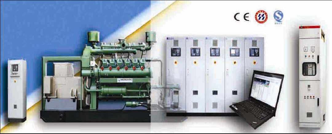
The FCP1-TEM2 control panel operating with the GCBP Generator Current Breaker is served as the electric control system in the natural gas generator set. The control panel functions protections to overload, over current, short circuit, reverse power, under or over frequency, under or over voltage and high or low storage battery voltage beside that it may conduct monitoring, alarm, auto tripping and engine shutdown to cylinder temperature, lube oil temperature, oil pressure and over speed if these happen in the primary engine. The FCP1-TEM2 control panel shall be a good choice for the natural gas generator set because of its perfect factors like perfect view, compact structure, simple operation, safety and reliability and complete monitoring and control capacity.
|
rate power(kW) |
700 |
|
Field control panel |
type |
FCP1-TEM2-700T |
|
size |
800├Ś600├Ś1800 |
|
Breaker control panel |
type |
GCBP |
|
size |
800├Ś800├Ś2200 |
|
Rate voltage(U) |
400 |
|
Rate current(A) |
1263 |
|
Rate frequency(Hz) |
50 |
|
Power factor |
0.8 |
Field Control Panel
1 Functions
FCP1- 700T field control panel functions protections to the generator set and prevent against damage which may result from overload, over current, short circuit, reverse power, under-frequency, over frequency, under voltage, overvoltage and high or low battery voltage, additionally, it can also provide monitoring to cooling water temperature, oil temperature, oil pressure, speed and mixer opening, water level in water radiator, oil level ion oil sump and raise alarm or bring an automatic fault shutdown.
The intelligent AIO-NT of ComAp main control module and the IS-DISPLAY is integrated to provide the complete operation and management to the gas generator sets. Combined with the speed governor and AVR, this module achieves the quasi-paralleling and automatic power factor, and allows One-Touch Start with only a single press of the button and automatic regulation of air and fuel ratio.
1.1 Parameters Measurement and Protection
The system displays parameters with graphs or digits by a big LCD. Complete parameters are measured including three-phase voltage, three-phase current, power, power factor, frequency, load & power factor of customers; accumulated genset electricity, accumulated operating hours, storage battery voltage and engine operating status including exhaust temperature and 12-cylidner temperature, oil pressure before/after filtering and turbocharger, engine speed, temperature soft circulation water, engine room and oil sump, after-cooling mixture gas and winding, pressure of after-cooling mixture gas, high/low temperature water return as well as carburetor opening feedback and others.
The system will raise alarm subject to the over-limit status described in the above mentioned parameters. The three-grade alarms are prepared in the system involving in the accouse-optic, switch-off and engine shutdown. All alarm values have been set in the factory, and never modify these parameters unless it has been permitted by the technicians.
1.2 Controlling of Generator Set
The control system consists of a main controller AIO-NT, a display module IS-DISPLAY, a voltage change module IG-AVRI, DC power and control relays and more, bringing control to the engine including Start and Stop, Switch-On/off of relays, automatic regulation of voltage, power factor, speed and load, automatic switch-on/off of synchronization and others. Please read the manuals of AIO-NT and IS-DISPLAY for detail information.
1.2.1 Voltage Setting
Automatic voltage regulation of the generator set is functioned by the main controller AIO-NT, a voltage interface module IG-AVRI and voltage change module IG-AVRI-TRANS. Voltage may be adjusted manually through the voltage setting potentiometers according to the actual situation.
1.2.2 Automatic Synchronization
The generator set is synchronized automatically to power grid. During synchronizing, the main controller analyzes electric parameters between the bus-bar and generator sets, and detect whether the differential amplitude and the phase angle between the genset and the power grid fall within the required values, i.e. whether both parts are synchronous, if not, the main controller will change the voltage and frequency of the generator set automatically. When the required synchronous values arrive, the main controller will send out a switch-on signal automatically to have the genset breaker closed.
After being connected to the power grid, the main controller will adjust the excitement current automatically according to the setting value of power factor and keep the power factor within the set range.
1.2.3 Speed Governing System
The speed governing system consists of the Woodward electronic speed governor, speed sensor and actuator. For details, refer to the relative manuals.
1.2.4 Alarm
It is critical to monitor parameters of the genset operating status. When alarm occurs, the main control module will send out corresponding actuating signals according to different types of alarms. This part consists of an AIO-NT, alarm relay, alarm horn and alarm indicators. When fault alarm occurs, AIO-NT will pop out the alarm menu, indicate alarm elements and record automatically operating parameters of the generator set for customers review later.
The main controller AI0-NT will achieve these protections including high temperature, high exhaust temperature, over-speed, high cooling water temperature, low oil pressure, overload, over current, short circuit, reverse power, under or over frequency, under or over voltage, excessive high or low battery voltage and others.
When alarm fault occurs, the alarm indicator lights and sounds, and the main controller AIO-NT will send out corresponding signal like alarm, breaker switch-off or shutdown. Press the Horn Reset button in the AIO-NT to eliminate the alarm. Explore and correct the fault and reset by pressing the button of Fault Reset button in the AIO-NT. As for parameters and alarm control functions that the panel will provide, please see table 1.
Table 1 Protection and Control Parameters
|
No. |
Protection Description |
Alarm Description |
Actuation Delay Time |
Switch -Off |
Shutdown |
|
|
High water |
greater than or equal 85 C Degree, alarm |
5 S |
No |
No |
|
1 |
temperature |
greater than or equal 90 C Degree, alarm and unload |
5 S |
Yes |
No |
|
|
oil |
greater than or equal 90 C Degree, alarm |
10 S |
No |
No |
|
2 |
High temperature |
greater than or equal 95 C Degree, alarm and unload |
10 S |
Yes |
No |
|
|
Low oil pressure in |
less than or equal 0.300MPa, alarm |
5 S |
No |
No |
|
3 |
the main oil gallery |
less than or equal 0.250MPa, alarm and shut down |
0 S |
Yes |
Shutdown |
|
4 |
High differential pressure |
greater than or equal 0.150MPa, alarm |
5 S |
No |
No |
|
|
|
greater than or equal 500 C Degree, alarm |
5 S |
No |
No |
|
5 |
High cylinder temperature |
greater than or equal 600 C Degree, alarm and shut down |
3 S |
Yes |
Shut down |
|
|
High exhaust |
greater than or equal 600 C Degree, alarm |
5 S |
No |
No |
|
6 |
temperature |
greater than or equal 650 C Degree, alarm and unload |
5 S |
Yes |
No |
|
7 |
Reverse power |
greater than or equal 10% rated power, alarm and unload |
10 S |
Yes |
No |
|
|
|
greater than or equal 112%rated speed, |
|
|
|
|
8 |
Over speed |
alarm and shut |
0 S |
Yes |
Shut down |
|
|
|
down |
|
|
|
|
|
|
greater than or equal 115 % rated |
|
|
|
|
9 |
Over load* |
power, alarm and |
10 S |
Yes |
No |
|
|
|
unload |
|
|
|
|
|
|
|
|
|
No |
|
|
|
greater than or equal 110 %rated |
|
|
|
|
10 |
Over current* |
current, alarm and |
40 S |
Yes |
|
|
|
|
unload |
|
|
|
|
|
|
Overload long time delay |
Ir1=0.85 of rated genset current, alarm and unload |
t1=15 S |
Yes |
No |
|
11 |
Four types of breaker protections |
Short circuit short time delay |
Ir2=5Ir1 alarm and unload |
t2=0.1S |
Yes |
No |
|
|
|
Instantaneo us short circuit |
Ir3=8Ir1 alarm and unload |
t3=0 S |
Yes |
No |
|
|
|
Earth fault |
Ir4=0.2In alarm and unload |
t4=0.2 S |
Yes
|
No |
|
|
|
F less than or equal 96%of rated |
|
|
|
|
12 |
Under frequency |
genset frequency, |
5S |
Yes |
No |
|
|
|
alarm |
|
|
|
|
|
|
f greater than or equal 10%of rated |
|
|
|
|
13 |
Over frequency |
genset frequency, |
5S |
Yes |
No |
|
|
|
alarm |
|
|
|
|
14 |
Under voltage |
less than or equal 85%of rated genset voltage |
5 S |
Yes |
No |
|
15 |
Over voltage |
greater than or equal 115% rated voltage, alarm and unload |
5 S |
Yes |
No |
|
16 |
High winding temperature |
greater than or equal 140 C Degree, alarm and shutdown |
0 S |
Yes |
Shutdown |
1.2.5 One-Touch Start and Automatic Air Fuel Ratio Regulation
When the system has been ready for starting, it is only needed to press the START button. The system achieves automatic Start, Stop and Power Management. The system will regulate automatically the air/fuel ratio according to the built-in power curve and enable the generator set to accommodate with a variety of the gases. The remote control unit and central monitoring unit used in the system bring a remote control and monitoring to the generator set.
1.2.6 Neutral Control (Optional)
The system will control neutral according to the actual operation of the generator set. While single generator set runs, the neutral contactor closes when genset voltage is higher than 75%. As the single generator set stops, the neutral contactor opens when the genset voltage is lower than 50%. When several gensets operate in parallel, the neutral contactor is closed on running genset with the lowest Control Address only, and others neutrals open. For details, refer to the instructions and information on AIO-NT.
2 Front Panel
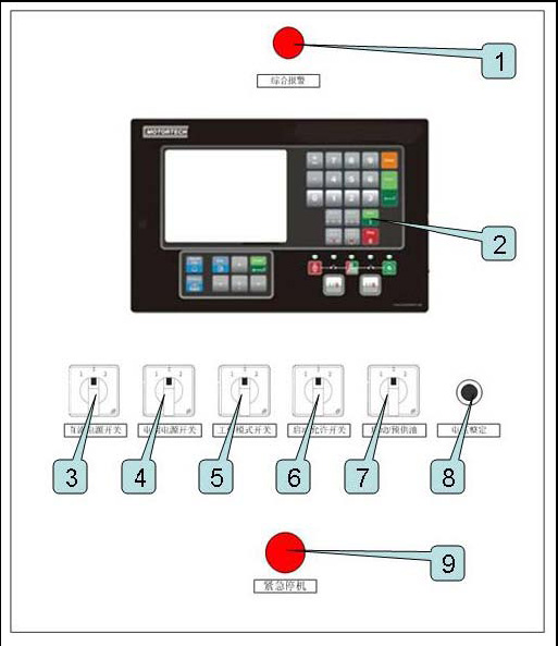
Fig. 1 Front Panel of Field Control Panel
The front panel of the field control panel includes the following devices.
1) The optoacoustic alarm that functions alarm when faults occurs when the generator set is in operating.
2) A display (IS-DISPLAY) that is display main parameters of the generator set. For details, refer to the
instruction manual.
3) A DC power switch that is used as a master power switch of the control panel.
4) A power switch t, hat is used as the electronic speed governing system and its devices.
5) Operation Modes of MANŌĆōOFFŌĆōAUT is provided to choose the genset operating mode.
6) The control button of NO /YES that is used to control if the generator set starts or not.
7) The button of PRELUBE- OFF-START that is used manually to pre pump oil to the engine.
8) A voltage/power factor setting potentiometer (VOLTAGE SETTING) that brings manual adjustment of
genset voltage or power factor.
9) An EMERGENCY BUTTON that is used to stop the generator set in emergent situations.
Generator set Circuit Breaker Panel
1 Functions
For the GCBP breaker panel, the intelligent main breaker produced by CHANGSU Company has been used, which is characterized with draw out construction complete intelligence, high break, zero arc and isolation and easy operation, therefore it enables the generator set to supply power reliably.
2 Front Panel
The genset breaker panel is structured in upper and lower parts. Controls to the genset breaker are achieved in the upper part of its front panel. See figure-2 about its layout.
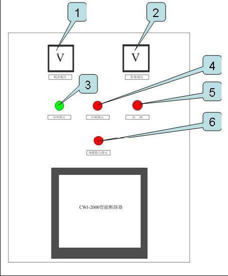
Figure-2. Upper Front Panel of the Genset Circuit Breaker Panel
1) The V-Genset Voltmeter indicates genset voltage. 2) The V-Mains Voltmeter indicates mains voltage.
3) The SWITCH-OFF Indicator lights up when the genset breaker opens. 4) The SWITCH-ON Indicator lights up when the genset breaker closes. 5) The SWITCH-OFF Button is used to open the mains breaker. 6) The N-line-ON Indicator lights up when the N-line contactor closes.
.site commission, date of delivery and terms of payment
A. Site commissioning
Site commissioning of the power generator set will be conducted by qualified engineers; buyer should cover engineers’┐Į?insurance cost, round ticket and accommodation.
B. Date of delivery
Within 65 days after receiving down payment, EX Work delivery
C. Terms of payment
30% of total value as down payment and paid after signing contract, the rest 70% will be paid before delivery.
FOR MORE GE GAS TURBINE SPARE PARTS, PLEASE CLICK.
|

