|
Starting motor |
ST70, 11kW, 24V |
|
Turbocharger |
SH85B, Radial flow type;
Flow capacity: 0.6kg/s
Speed: 42,000rpm |
|
Air filter |
Paper element, 2400m3/hour, 3.2kPa pressure drop |
|
Water pump |
Centrifugal type, 1,900rpm, 1,000L/min, 20m lift |
|
Oil cooler |
Water cooled, fin-type |
|
Centrifugal oil filter |
5,000rpm, 16-18L/min (oil temp. at 75�?/SPAN>, oil pressure at 600kPa) |
|
Oil filter |
Paper element, 200kPa pressure drop |
|
Natural gas pressure regulator |
FISHER, FSS202CMB |
|
Magneto |
Type: ALTRONIC �?/SPAN> ; Model: 12A33H-A Made in America |
|
Ignition coil |
Manufacturer: ALTRONIC Made in America |
|
Spark plug |
STITT 807BEX13.5, Made in America |
|
Mixer |
IMPCO 200T-1 |
|
Speed governor |
WOODWARD, 2301A, Full electronic, 24VDC Made in America |
|
Manufacturer |
|
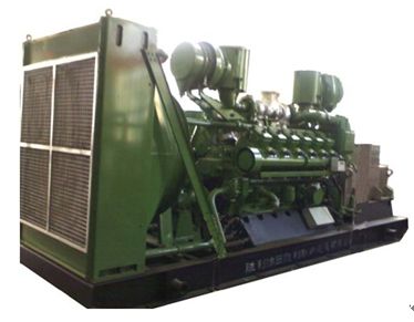
SD Gas Engine |
|
Engine type |
|
12V190ZLDK |
|
Working principle |
|
4-stroke, with turbocharger and intercooler |
|
Configuration |
|
Vee 60° |
|
No. of cylinders |
|
12 |
|
Bore |
mm |
190 |
|
Stroke |
mm |
210 |
|
Mean piston speed |
m/s |
7 |
|
Compression Ratio |
|
9: 1 |
|
Total displacement |
L |
71.45 |
|
Torque Max. |
N.m |
5265 |
|
Rated power |
kW |
550 |
|
Rated speed |
r/min |
1000 |
|
Filling capacity of lube oil |
L |
180 |
|
Lube oil pressure in oil main line |
kPa |
400-800 |
|
Lube oil pressure in turbocharger |
kPa |
200-400 |
|
Stable speed droop |
% |
�? |
|
Cylinder serials number |
Flywheel on left |
1 - 2 - 3 - 4 - 5 - 6
7 - 8 - 9 -10 -11 -12 |
|
Ignition method |
|
Spark Plug Ignition |
|
Ignition order |
|
1-8-5-10-3-7-6-11-2-9-4-12 |
|
Starting method |
|
24VDC motor |
|
Direction of Rotation |
Flywheel view |
Counterclockwise |
|
Power output method |
|
Flywheel output |
|
Cooling system |
|
Radiator with blower fan |
|
Length |
mm |
2692 |
|
Width |
mm |
1560 |
|
Height |
mm |
2070 |
|
Weight empty |
kg |
5330 |
Thermal Data
|
Exhaust temp. Before turbocharger max. |
°C |
�?30 |
|
Lube oil temp. |
°C |
�?0 |
|
Jacket water temp. |
°C |
�?5 |
Exhaust Gas Data
|
Exhaust temp. Before turbocharger max. |
°C |
�?30 |
|
Nominal exhaust temperature |
°C |
550 |
Lubrication Oil Consumption�?.0 g 15W40CD
2.3 Technical data of alternator
|
生产�?/FONT>
Manufacturer |
|
中船重工电机科技股份有限公司
CSIC Electrical Machinery Science & Technology Co.,Ltd |
|
型号
Model |
|
1FC6 456-6LA42 (Dust proof type) |
|
规范和冷却介质温�?/FONT>
Specification and temp. of cooling medium |
|
VDE40°C |
|
额定电压�?/FONT>V
Volt. |
V |
400 |
|
额定电流�?/FONT>A
Rated Current |
A |
902 |
|
额定功率�?/FONT>KVA
Rated power |
KVA |
625 |
|
功率因数
Power factor |
|
0.8 (lag) |
|
转��?/FONT>r/min
Rotation Speed |
r/min |
1000 |
|
频率�?/FONT>Hz
Frequency |
Hz |
50 |
|
防护等级
Protection degree |
|
IP23 |
|
绝缘等级
Insulating Class |
|
F |
|
接线方式
Phase and co |
|
三相四线�?/FONT>
3 phase-4 wire connection |
|
励磁方式
Exciting method |
|
无刷相复励磁
Brushless excitation |
|
冷却方式
Cooling method |
|
空气自然冷却
Natural cooling |
Product description
The brushless constant-voltage synchronous alternators are of the self-excited type with an electronic voltage regulator integrated in the excitation system. They are used as main or standby units in landbased power installations and for ships' electrical systems and can be driven by internal combustion engines or gas, steam and water turbines and electric motors.
Structure:
The alternator comprises the main machine, exciter and excitation system. The main machine is of revolving magnetic field with cylindrical rotor and damper winding.
The exciter is revolving armature machine.
The exciter power is supplied to the rotor of the main machine via rotating rectifiers.
1FC6 Series have open-circuit cooling, 1FJ6 Series have close-circuit circulation cooling.
Standards and Specifications:
1FC6/1FJ6 Series confirm to applicable IEC requirements,DIN standards and VDE specifications and particularly to VDE0530, specifications for rotating electrical machines. They can also be made to comply with China's national new standards and following foreign standards and requirements. BS2613 and BS5000
NF C51-100
CSA C22.2-100
CEI 2-3
Other standards are on enquiry.
The alternators excitation devices accord with Group C requirements stipulated in the VDE0660 AND VDE0110.
In the process of the "Jieli" generator development in more than 10 years, leaders from the China Shipbuilding Industry Corporation and its subsidiary corporation in every area came to our plant many times to guide work and gave strong support to the plant. Their actions are helpful for the plant's 1FC6/1FJ6 genertors and diesel generating sets to rapidly get big market share. The generator industry realized the transitional development from weak to strong.
The brushless synchronous alternators for marine use be made with introduced Siemens Licence.
The plant signed “The Agreement for Use of Siemens Global Services? with the Siemens AG of Germany for 1FC6/1FJ6 generators.
We'd like to meet the users' demands to the maximum limit by supplying high-quality products and satisfactory service.
Output
The rated outputs( KVA)given in the Selection Table are valid for:
---Continuous running duty at 50 or 60Hz rated frequency.
---Power factors from 0.8 to 1.
---Class F insulation.
---Sinusoidal load current.
---Symmetrical load.
Site rated output:
Corrections must be made from the nominal output to VDE0530(rated output at 40°C and 1000m a.s.l)in each of the following cases:
1.Coolant temperature exceeds 40°C and marine alternators regulated by different classification society rules(See Selection Tables).
A special inquiry should be made if the coolant temperature exceeds 55°C. At coolant temperature 30°C the mean output is increased by 4% over that permissible at coolant temperature 40°C.
2.Site altitude exceeds 1000m a.s.l.(Does not appall for marine alternators), the output will reduce as following table.
|
Site altitude (m)a.s.l. |
1000 |
1500 |
2000 |
2500 |
3000 |
3500 |
4000 |
|
Permissible output % of rated value |
100 |
97 |
94 |
91 |
87 |
82 |
77 |
If no coolant temperature is stated, it will be assumed that the altitude-induced reduction in the cooling efficiency is compensated by a lower coolant temperature i.e.that adjustment of the maximum temperature rise stipulated in VDE0530 is not necessary(No derating). The following coolant temperatures are obtained for the thermal utilization corresponding to class F insulation.
|
Site altitude(m�?/SPAN>a.s.l. |
1000 |
1500 |
2000 |
2500 |
3000 |
3500 |
4000 |
|
Coolant temperature in °C |
40 |
35 |
30 |
25 |
19 |
14 |
9 |
3.If power factor is less than 0.8, the output will reduce as following table.
|
Power factor cosphi |
0.8 |
0.7 |
0.6 |
0.5 |
0.4 |
0.0 |
|
Permissible output % of rated value |
100 |
96 |
92 |
91 |
90 |
88 |
4.Unbalanced load In accordance with VDE0530, the alternators can withstand unbalanced loading of up to 20%. It should be noted however, that the voltage variation and the rated outputs indicated in the tables are not attained under unbalanced load.
5.Overload In accordance with VDE0530, the alternators can have an overload of 1.5 times the rated current at rated voltage for 2 min.
Voltage and frequency:
The alternators are suitable for operation at 50Hz and at 60Hz as shown in the Selection Tables. The alternator voltages are 400V at 50Hz and 450V at 60Hz. Load voltages corresponding to the alternator voltages are 380V at 50Hz and 440V at 60Hz.
Apart from an internal reference value potentiometer on the regulator the rated voltages can be adjusted ±5% using an external panel mounting reference value setter(optional extra).
The three-phase stator winding of the alternators is connected in star. The neutral point is brought out.
Efficiency
The efficiency given in the Selection Tables allows for the total losses in the alternator, including those of the field winding and excitation system. The value at rated output are guaranteed in accordance with VDE0530.
Insulation system
The alternator windings are equipped with Siemens DURIGNIT®2000 insulation system which meets Class F requirements to VDE0530.
The insulating materials used are non-hygroscopic, non-tracking and withstand severe thermal stressing.
The stator winding of the alternators are made of special enameled wire of high hydrolysis-resisting quality or flat copper bars with mica paper.
A special resin impregnation process is adopted to the standard insulation. This results in high mechanical strength, vibration resistance and excellent dielectric strength and renders the alternators suitable for operation in all climates to DIN50 019.
Radio interference suppression
The alternators are equipped with interference suppression in accordance w ith grade N of VDE0875 and suppression level K is on request.
Ex citation system
Th e alternators are fitted with thyristor voltage regulator THYRIPART®excitation system. The excitation current can be regulated automatically in accordance with the variation of load, resulting in constant voltage. This style of excitation has excellent kinetic character in the conditions of load-variation and short-circuit.
Speed and direction of rotation
At rated speed given in the Selection Tabes the alternator produces the rated frequency of 50/60Hz.
The alternators are of clockwise running when viewed from the drive end. They can also be supplied as anti-clockwise running on request.
In accordance with VDE0530 the sequence "U,V,W" of the terminals in the terminal box corresponds to the phase sequence in clockwise rotation. For operation in parallel with an existing system the phase sequence must be checked before making the connections.
Over speed for alternators nomally Nmax=1.2nN, higher values on request. With the alternator main switch open there are no restriction on operation the alternators with THYRIPART? excitation at less than rated speed (e.g.d for starting -up the prime mover). This does not apply to special alternators with sleeve bearings which may only be run down to about 20% of their rated speed.
Standards and Specifications:
The alternators can be supplied in the following versions to IEC34-7.( IM=international mounting ).
DIN 42 950 designations are in brackets.
Alternators 1FC6 184 to 354 can be easily adapted to various mounting situations by the feet mountings on the housing. They can aslo be supplied without feet.
If requested, frange dimensions other than those quoted in the dimensions tables can be suppplied, please give flange diameter N and flange depth R.
Degree of protection
1FC6 series alternators normally have degree of protection IP23( DIN 40 050 ). The 1FJ6 45.-56. alternators have degree of protection IP54/IC81, according to IEC(IC81: closed circuit cooling system with built-on air/water cooler ).
The terminal box or terminal space has degree of protectionIP54.
Other detrees of protection on enquiry.
Air filter
An air filter can be fitted for special conditions on request.
If customer calls for air filters, it is recommended that thermistor sensors are fitted in the stator winding so that if a temperature rise occurs due to a dirty filter, an alarm or shutdown can be given.
Anti-condensation
Anti-condensation heating is available for the alternators(as an optional extra).
The anti-condensation heater requires a voltage of 220V or 110V and has heat output of about:
80W for 1FC6 184 to 286
150W for 1FC6 350 to 408
315W for 1FC6 454 to 566
Terminals and connection bus-bars
Cable entry to the 4 main connections,(U, V, W, N )and to the 2 field terminals( F1, F2 ) can be from left or right. The cable entry plates normally supplied undrilled.
Paint finish
Alternators are painted with polyurethane mica ferric oxide red bottom lacquer and sea-gray polyurethane face lacquer(marine)or light tan-gray alcohol acid magnetic lacquer( land ) ,special painting requirements should be declared in orders by customers.
Moment of inertia
All values for the moment of inertia(J in Kgm2) given in the Selection Tables are subject to a tolerance of ±10% conformed to VDE0530, the values are for the rotor without coupling.
Cooling
The alternators are internally cooled with shaft-mounted fan to VDE0530, IEC IC01, the fan provided at the drive-end draws the cooling air axially through the machine.
Noise emission
The alternator noise level does not exceed that stipulated in VDE0530B part 9.
Vibration
Reciprocating engines used as prime movers impress vibrations on the alternator because of the pulsating torque output. Permissible vibration streeing accords to DIN6280-11.
Please enquire if higher viberation stressing levels are expected.
Bearings
See "spare parts" page for bearing allocations. Alternators up to 1FC6 286 have on-off lubricated bearings,1FC6 35. and above can be re-lubricated during operation.
If required, alternators 1FC6 454 and larger can be fitted with sleeve bearing, please enquire.
With alternators 1FC6 350 and larger, a miniature Pt100 screw-in resistance thermometer can be
fitted in the bearing for, r, em, ot, e , display.
Drive and coupling
Alternators provided with two bearings can be driven by reciprocating engines via highly flexible couplings.
The coupling is not part of the scope of delivery of the alternator manufacturer.
The torsional vibration has to be calculated for rigidly coupled single-bearing alternators. We can provide dimension and axis-system drawing. Any axis-system special requirements are on enquiry.
Steady-state voltage variation
Throughout the range from no-load to rated power factor, the following voltage regulating accuracies are achieved:
Isolated operation(without droop compensation device) UN±0.5%
Parallel operation(with droop compensation device) UN±2.5%
On alterantors equipped with droop compensation the voltage variation in parallel operation can be improved to the isolated-operation value by short-circuiting the droop compensation device.
Failures in the excitation unit do not result in the voltage rising to more than 115% of the rated voltatge.
Voltage variation on connecting and disconnecting a load
The voltage will suddenly drop or rise when loading or unloading suddenly.
The variation of voltage versus rated voltage as follows:
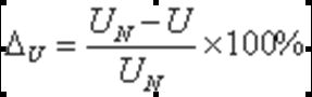
UN--rated voltage of alternator
U-lowest ( highest ) voltage after loading or unloading suddenly
The variation approximate assessment of the average value is :
Short-circuit current and short-circuit rating :
Due to the load-dependent operation of the static excitation system the alternators meet the requirements for lowest possible voltage dips and fast voltage recovery after sudden loading with large squirrel-cage induction motors. The excitation principle used provides sustained short-circuit currents of approximately 3 to 5 times the rated current. This enables the use of selective protective relaying. The alternators must be relieved of the sustained short-circuit current after 5s.
The magnitude of the sudden short-circuit current referred to the rated output to VDE0530 at 40°C(see column 1 of the Selection Tables)satisfies the requirements of VDE0530.
Unbalanced load
In accordance with VDE0530, the alternators can withstand unbalanced loading of up to 20%. It should be noted however, that the voltage variation and the rated outputs indicated in the tables are not attained under unbalanced load.
Overload
In accordance with VDE0530, the alternators can have an overload of 1.5 times the rated current at rated voltage for 2 minutes.
Parallel operation
Continuous parallel operation is feasible but please bear in mind the following points:
1.All alternators are provided with a damper winding which reduces phase swinging in parallel operation.
2.The active-load sharing is adjusted by using the governor of the driving engine. The speed characteristic of the engine should be linear and in coincidence and on changeover from rated load to no-load the speed should rise by at least 3% and by not more than about 5%.
3.The reactive-load sharing is assured by a droop compensation device. A droop compensation device can be supplied for alternators 1FC6 18. for switchboard panel mounting.
Droop compensation devices can be fitted in alternators 1FC6 22.-35.if requested and is available in 1FC6 40.-56. alternators.
Thus equipped, the alternators are suitable for parallel operation with other alternators having the same voltage droop or with a supply system.
4.Neutral point connection
Direct interconnection of alternator neutrals and/or those of transformers and load neutrals may give rise to circulating current of three times the power frequency in the neutral conductor. The magnitude of these currents must be measured in the alternator neutral conductor under the highest conceivable load conditions. To avoid thermal overloading of the alternators the circulating currents occuring at three times rated frequency should not be allowed to exceed about 50% of the alternator rated current.
Over high current values should be limited by means of neutral reactors or other equivalent means.
Alternator protection equipment
The stator winding can be equipped with thermal protection in the form of PTC sensors or resistance thermometers. Please enquire where alternator protection gear necessitates opening of the neutral. Please quote type if it is intended to use a star-point current transformer.
Alternators to be operated in parallel should be provided with reverse-power protection.
The necessary monitoring and tripping devices must be provided separately and are not included in the alternator scope of supply.
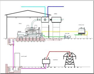
Engine operation, synchronization and protection: Control Panel system
|
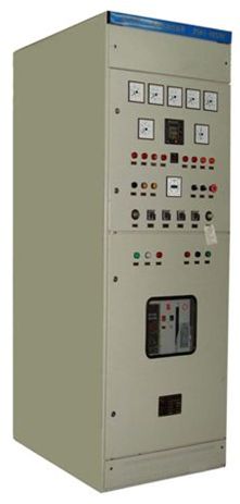 |
Displays data of: voltage of each phase of the alternator, current of each phase, power output, power factor, frequency; voltage of each phase of the grid; total power output calculation, total operation time, engine speed, cylinder temperature from cylinder 1 to 12, exhaust temperature from cylinder 1 to 12, lube oil temperature, lube oil pressure, turbo charger oil pressure, water temperature,
|