|
10x6790kw MAN 14V32/40 HFO Diesel Generator plant proposal
The Technical Program of Nigeria 65 MW DG
HFO Power Station
10x6790kw MAN 14V32/40 HFO Diesel Generator plant
China National Electric Wire & Cable Imp./Exp. Corp.
Contents
OUR PRODUCER, founded in 1995, registered capital 185,000,000, headquarted in Yiwu, Zhejiang Province, is an external enterprise specialized in the research and development, manufacturer, sales and service of diesel generators. Because of the products, technique and service of OEM cooperation with German MTU, UK Perkins, South Korea DOOSAN,USA Marathon, France Leroysomer and other world-known enterprises, the emergency electrical stations provided electricity guarantee for Dubai Electricity and Water Authority (DEWA)�?9680KW�?Xiangguang Copper(4800KW), Jiangxi Copper Group(3200KW),China Financial Center Database(11000KW),Jiangxi LDK Solar (5600KW),etc. The factory of Hangzhou, established in April, 2005, is situated in Hangzhou Economic and Technological Development Zone, with a floor area of 50,402 square meters and the total investment of US$59.6 million. On October 11th, 2006, OUR PRODUCER signed a license agreement of technology acquisition and collaborative production with MAN Diesel Group to become a licensed member, specialized in producing MAN Diesel high-power, medium speed, four-stroke engines, auxiliaries and propulsion system with the power ranging from 1000kw to 10,000kw. Supervised by the experts designated by MAN Engine Company, the products all passed MAN product quality inspection, Ship Classification Society OF CCS and BV. On June 20th, 2009, the first 32/40 4500KW engine held a ceremony, released to the users and realized the production. The company plans to produce 20 engines in 2009 and 100 engines in 2010. The company dedicated to research and exploration of heavy fuel oil power station, supported by the technology and products of MAN and the over ten-year experience of emergency power station. In May,2009, signing an agreement of the heavy fuel oil power station South American market development, the two sides plan to design, construct and operate Brazil 174Mwand 200MW heavy fuel oil power station, which got technology and supporting services from MAN.
Equipment, parts and auxiliary equipment, provided by the seller, correspond with the latest version of the standard, but they are not limited to the following standard:
2.1 State Standards
GB2820�?997 《Alternated current drive reciprocating internal combustion engine generating sets�?/DIV>
JB/T10303-2001 《Technical conditions of power frequency diesel generating sets�?
GB755�?000 《The basic technical requirements of electric rotating motor�?/DIV>
GB1105�?987 《Performance testing method of internal combustion engine housing�?/DIV>
GB1859�?000 《Internal combustion engine noise determination method�?/DIV>
GB3907�?983 《The basic measuring method of industrial radio interference�?/DIV>
JB/T8194-2001 《Vocabulary terms of internal combustion engine electrical station�?/DIV>
GB12699-1990 《Rated power, rated voltage and speed of power frequency diesel generating sets�?
CB/T3253-1994 《Technical conditions of marine diesel engine�?/DIV>
CB/T3254-1994 《Experiment of marine diesel engine housing�?/DIV>
GB8840-1988 《Exhaust limits of marine diesel engine�?/DIV>
2.2 Technical standards of MAN
Refer to ISO 30461/1-2002
The standard environmental condition
Environmental temperature: 25�?/DIV>
Barometric pressure: 1bar
RH (relative humidity): 30�?/DIV>
Fuel oil condition:
Fuel lower heating value: 42700 kJ/kg
Total capacity of power station: 65 MW
Voltage: 11kV
Frequency: 50Hz
PF (Power Factor): 0.8pf
5.1 Overall description of heavy fuel oil power station
There are 10 MAN 14V32/40 diesel generating sets in 65MW heavy fuel oil power station, each set power: 6790KW,total power: 67.9MW,
Voltage: 11kV
Frequency: 50Hz
PF: 0.8pf
Speed: 750rpm.
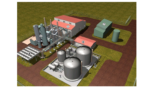
The design picture of standard electrical station�?/DIV>
�?Power station
�?Exhaust system and exhaust boiler
�?Sweetener
�?Radiated coolant system
�?Fuel depot
�?Pump station
�?Maintenance workshop and warehouse
65MW power station contains power station, exhaust system and exhaust boiler, radiated coolant system,fuel depot, pump station, maintenance workshop & warehouse and working building. Generating sets, auxiliary machines, supply unit, lube filtration separator and control system are all installed in power station. If you don't consider terrain factors influence, the ideal power station can take up an area of 200m×200m. While the actual station design could be adjusted by weather, environment and terrain, but principle of proximity should be considered to prevent too much a long pipe arrangement. At the same time, the heat of heavy fuel oil tank is realized through the vapor of exhaust boiler, so the short line is in favor of heat insulation.
There is the general layout of 65MW power station in the annex.
The heavy fuel oil could be the main fuel and light diesel oil the auxiliary fuel. With the main generating sets parallel operation, each unit can input or exit operation. The control system could adjust power balance, power of different sets, which has protective measures of inverse power, over current, etc.
(Suggestions) The power station need to collocate a 250kVA auxiliary engine, which can supply the black start power, light fuel oil, 24V storage battery start, power -0.4kV, frequency-50Hz, PF-0.8pf, and rotated speed-1500rpm. When the power station comes into good running, the auxiliary engine turns to the emergency standby sets.
Transformer, collocate by power station, provide the main auxiliary equipment with working power supply, the electricity of station lighting and domestic consumption.
5.2 Characteristics of HFO power station
(1) Highly-structured corollary equipment, flexible installation site and short construction period
The corollary equipment of heavy fuel oil generating sets is rather simple for little corollary equipment, small volume and light in weight. Compared with water turbine-generator set needed to dam, vapor generating set needed to boiler, fuel storage, and water treatment system, the diesel generating set has advantages of small occupation, high construction speed and low invest cost.
Modularity unit system used for heavy fuel oil generating sets, flexible arrangement according to the terrain, which is fit for construction of mountain area and mine area, subjected to small regional terrain restrictions.
(2) High thermal efficiency, low fuel oil consumption and low operation cost
The heavy fuel oil machine extended from diesel is the highest thermal motors of thermal efficiency, of which the effective thermal efficiency is 40%�?0%, the high-pressure steam turbine is about 20%�?0%, and combustion gas turbine is about 20%�?0%. So fuel consumption is rather low about 178g/kWh. The power station form applied with heat and power cogeneration, has the higher whole energy conversion efficiency, and the thermal power gets more fully used.
(3) The rapid starting and can quickly reach full power
The heavy fuel oil generating sets may use heavy fuel oil and light fuel, which could reach full loaded operation in 3 min of emergent condition (light fuel oil used on emergency ), and in 10 min of normal operation condition (starting uses light fuel oil, and heat engine uses heavy fuel oil ),while the thermal & electricity steam power equipment generally needs 3�?h from starting to full load. What’s more, the shutdown process of diesel is rather short, started and shutdown frequently.
(4) Simple maintenance, small conventional maintenance work, little operation staff, overhaul period of 36000h (related to the fuel oil quality), and low operation expense.
(5) Convenient unit combination, capacity easy to extended
Each capacity of MAN heavy fuel oil power station generating sets, ranging from 3000kw to 21000kw, which has the advantage of fitting for more power supply load with more selected capacity. When adopting heavy fuel oil power station generating sets as power, the installed capacity may dispose neatly according to actual need, which can increase power set capacity in the after enlargement & production. The expansion of access is simple and smart, so the expense of primary construction investment is much lower.
�?)Economy of power station operation
a、Fuel cost
MAN 14V32/40 generating sets adopted by this program, the fuel consumption rate is:
|
Rate of loading |
100�?/DIV> |
85�?/DIV> |
|
Fuel consumption rate |
181g/kWh |
179g/kWh |
|
Fuel consumption 1kWh |
186.6 g |
184.5 g |
Estimated with 180# heavy fuel oil, 1600 Yuan/ton
Generator efficiency 97%;
The fuel cost of 1kWh
|
Rate of loading |
100�?/DIV> |
85�?/DIV> |
|
1 kWh |
0.299RMB |
0.295 RMB |
b、Oil cost
When lube oil consumption rate is 0.8 g/kWh, generator efficiency is 97%, provided by MAN database, the lube consumption is 0.82 g/kWh.
c�?Maintenance cost
The heavy fuel oil power station has a long overhaul period that can reach 36000 hours in general condition. Counted by 20 hours per day it can operate over 5 years continuously.
With a mature model14V32/40 and low malfunction rate, it is widely used between the ship and power station domain. Also with plenty of spare parts storage and supply, the maintenance cost is rather lower.
|
No. |
Designation |
Contents |
Unit |
Qty. |
Installed location of machines |
Remarks |
|
1 |
OUR PRODUCER-MAN
14V32/40 generating sets |
Engine, shaft coupling, generator, public chassis, control panel |
set |
10 |
Power plant |
|
|
2 |
Auxiliary module |
Comprised by lubricating pump, lube oil cooler, lubricant temperature control valve, lube self-cleaned filter, high temperature pump, high water temperature control valve, low temperature pump, low water temperature control valve, control switch cabinet, etc. |
set |
10 |
With standby |
|
3 |
Lube separating module |
Including lube delivery pump, lube preheating device, lubricant separator, sump pump, sump tank, control switch cabinet, etc. |
set |
10 |
With standby |
|
4 |
Fuel supply module |
Conversion valve of heavy fuel oil and light oil, fuelmeter, viscosity control, fuel mixed tank, fuel pressure pump, HFO end heater, fuel cooler, fuel double filter, control switch cabinet |
set |
10 |
With standby |
|
5 |
Leakage oil & decontamination module |
Sludge pump discharge, fuel leaked oil tank, lube sludge tank |
set |
2 |
|
|
6 |
Engine preheating module |
Preheating high temperature water, lubricating oil |
set |
10 |
|
|
7 |
Inlet filtration muffler module |
Shutter, inlet filter, inlet muffler |
set |
10 |
|
|
8 |
Nozzle cooling module |
Radiator, centrifugal water pump, cooler, expansion tank, temperature control valve, filling equipment, control switch cabinet |
set |
10 |
|
|
9 |
Water maintenance module |
Radiator, centrifugal water pump |
set |
1 |
Pump plant |
|
|
10 |
Heavy oil separation module |
HFO delivery pump, HFO preheating device, Separator, sump pump |
set |
2 |
|
|
11 |
Air container |
Starting air container, working air container, pressure reducing valve |
set |
2 |
With standby |
|
12 |
Air compressor |
H.P. air compressor, L.P. air compressor |
set |
2 |
|
|
13 |
Radiator |
High temperature water and low temperature water radiating |
set |
10 |
Radiator |
|
|
14 |
Exhaust Muffler |
Exhaust Muffler |
set |
10 |
Outlet and exhaust boiler |
|
|
15 |
Exhaust boiler |
Boiler body, air manifold, water pump, control switch cabinet |
set |
6 |
|
16 |
Switch cabinet |
Switch cabinet of parallel generating sets |
set |
10 |
Power Distribution room |
|
|
17 |
Feeder cabinet |
Switch cabinet of total outgoing line |
set |
2 |
|
|
18 |
Neutral point arrester cabinet |
Neutral point grounding of generator |
set |
10 |
|
|
19 |
PT cabinet |
PT buscouple |
set |
1 |
|
|
20 |
DC panel |
|
set |
1 |
|
|
21 |
Power distribution cabinet |
Power consumers and distributors of each module system |
set |
3 |
|
Configure of power station system contains as follows:
Diesel generating sets
Lube system
Lube supply system
Coolant system
Nozzle cooling circulation system
Cooled water preheating module
Cooled water supply system
Fuel system
Inlet system
Exhaust system
Leaked oil & decontamination module
Compressed air system
Electrical equipment of generating set
Architectural Equipment(the buyer in charge�?/DIV>
The generating sets mainly include diesel, duplex bearing generator, high elasticity shaft coupling and public housing. Diesel and duplex bearing generator are connected by high elasticity shaft coupling, which are also supported and fixed by public housing.
Function of diesel generating sets:
Rated power-----------------6790kW
Rated speed------------------------750rpm
Rated voltage-----------------------------11kV
Rated frequency-----------------------------50Hz
PF(Power factor)-----------------------------0.8
Steady-state voltage adjusting rate-----------------------------≤�?.5%
Transient voltage adjusting rate-----------------------------20%�?15%
Sudden load changing voltage steady time-----------------------------�?S
Voltage fluctuation rate-----------------------------�?.5%
Steady-state frequency adjusting rate-----------------------------≤�?.5%
Transient frequency adjusting rate-----------------------------+10%�?7%
Sudden load changing frequency steady time-----------------------------�?S
Frequency fluctuation rate-----------------------------�?.5%
Waveform distortion-----------------------------�?%
The generating sets permit sudden increase 60�?and reduction 100�?once a time, and the function index can meets the requirement.
The generating sets as the main electrical power, no limitations for operation time, it can operate and supply electricity continuously except the normal maintenance. In the operation process, the period can permit the overload operation of one hour per 12 hours, and if it overloads 10%, the function of the sets doesn’t fall.
7.1.1 Diesel
Brand and model of diesel-----------------------------MAN 14V32/40
Pattern-----------------------------V, four stroke, direct injection, turbocharger, air cooled, compressed air starting
Cylinder bore-----------------------------320mm
Stroke-----------------------------400mm
Bore spacing-----------------------------630mm
Compressed ratio-----------------------------14.5
MCR (Most Continuous Power)\speed-----------------------------7000kW/750 r/min
Direction of rotation-----------------------------Crankshaft clock-wise rotation (as viewed from output end)
Lowest steady speed-----------------------------250r/min
Fuel consumption rate (When MCR happens)�?....-----------------------------181g/kW.h,tolerance+5%
MEP (Mean effective pressure)-----------------------------24.9Mpa
Pistons mean speed-----------------------------10m/s
Air intake flow-----------------------------6.8kg/kW.h
Exhaust gas flow-----------------------------7.0kg/kW.h
Exhaust gas temperature after supercharger-----------------------------�?54�?nbsp;
Supercharger air pressure-----------------------------0.404MPa (Absolute pressure)
Supercharger air temperature before cylinder-----------------------------43�?nbsp;
Exhaust main pipe temperature before supercharger…��?�?65�?
Exhaust temperature of every cylinder-----------------------------�?10�?/DIV>
Most combustion pressure----------------------------------------------------------19.0Mpa
Diesel inlet lube pressure-----------------------------0.4�?.5MPa
Diesel inlet lube temperature-----------------------------65�?nbsp;
H.T. water into-machine pressure-----------------------------0.3�?.4MPa
H.T. water out-machine pressure-----------------------------90�?nbsp;
Injector coolant water into-machine pressure…�…�.-----------------------------0.2�?.5 MPa
Injector coolant water into-machine temperature …�…�…�..60�?nbsp;
Fuel into-machine pressure-----------------------------0.4�?.8MPa
7.1.2 Generator
Brand of generator-----------------------------LEROYSOMER
Generator output power\speed-----------------------------7000kW/750 r/min
Direction of rotation-----------------------------Counter clock-wise (as viewed from input end)
PF-----------------------------0.8
Voltage, frequency-----------------------------11kV 50Hz
Efficiency-----------------------------97%
Grade of Protection-----------------------------IP23
Winding temperature sensory-----------------------------2×6Pt100 (sensory) (1 set standby)
Anti-freezing heater-----------------------------AC230V
Coolant method-----------------------------Self-fan coolant
AVR (Automatic Voltage Regulator)-----------------------------Installed on generator
7.1.3 High elasticity shaft coupling
Connect the diesel and generator elastically in order to make sure the output power from diesel deliver to generator.
Model-----------------------------CRS3420
7.1.4 Public housing
Fix and support diesel and generator, internally install lube working oil tank and contain lube for diesel.
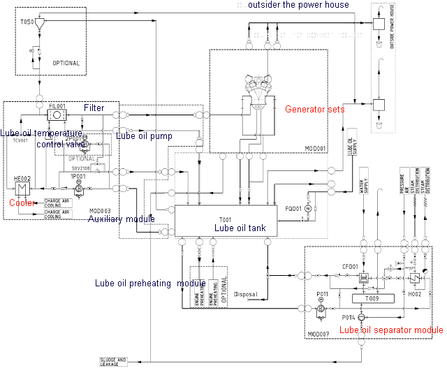
Lubricant system provides sets with lube of regular flow, temperature and quality, in order to lubricate and cool bearing, operation parts and piston. With separation, filtration and fresh supplement of lube, it can guarantee the function of set lube.
Lubricant system is a closed circulation system that connects atmosphere with crankcase breather, as shown in Figure1.
Outside the power house
Figure 1: The principle diagram of lubricant system
Lubricant system contains lube working tank, lube oil pump, lube cooler, lube temperature control valve, lube oil filter, lube pressure regulating valve, lube preheating module and lube cleaned separating module, etc.
7.2.1Lube working tank
Installed public housing of generating sets internally. When the generating sets operate, the oil level must be between upper limit and bottom limit of working tank.
Capacity of lube-----------------------------9 m3
7.2.2Lube oil pump
Lube oil pump has gear type and screw pump, which can make circulation by the lube. Installed safe relief valve internally to prevent the high system pressure. And lube oil pump drives by motor, one standby one uses.
Flow-----------------------------180 m3/h, 8 bar
7.2.3 Lube cooler
Lube cooler is panel cooler to take accumulated heat of system.
Heat exchange-----------------------------680 kW
7.2.4 Lube temperature control valve
Lube temperature control valve uses for maintain the constant temperature of system or the change within the small range of system temperature.
Control temperature -----------------------------65�?/DIV>
7.2.5 Lube oil filter
Lube oil filter can protect the diesel, which can keep off the impurity and lies in the entrance of diesel lube oil. Also the lube oil filter is continuous cross flow current kick-type self-cleaned filter.
Nominal filter fineness-----------------------------34μm
7.2.6 Lube pressure regulating valve
Lube pressure regulating valve is to regulate the system power of the operation process, which can make the inlet lube within the certain range of pressure of diesel.
Regulating pressure-----------------------------4-5bar
7.2.7 Lube preheating module
Parallel connection with the main lube system, it may preheat the lube of working tank to guarantee the rap is starting or sudden load. Generally, high temperature coolant water system and lube oil system are preheated with the same module.
Preheating temperature-----------------------------40 �?/DIV>
7.2.8 Lube cleaned separating module
It is connected with the main lube system, very important, which includes lube delivery pump, lube preheating unit, lube separator, sump pump, sump tank, and control switch cabinet. Generally, it separates the moisture and harmful of lube oil dust with centrifugal oil separator.
Effective handling capacity-----------------------------2.25 m3
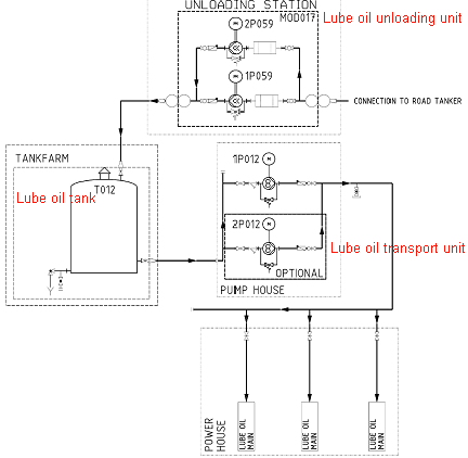
Lube supply system provide system with accepted, storaged and full lube to make the continuous operation of power station. The new lube is supplied by oil can or tanker truck. Then the workers can fill the tank of every lube working tank.
Figure 2: The principle diagram of lube supply system
Figure 2 is lube supply system including baggage hold oil of lubricant unit, lube storage oil can, lube delivery pump, lube capacity gauge, etc.
7.3.1The unloading oil unit of lubricant system
This unit mainly contains unloading oil pump, valve and granular filter. The unloading oil pump is gear type or screw pump that provides lube into storage tank from oil can or tanker truck, and drives by motor, one standby one uses.
The unloading oil flow-----------------------------25 m3/h�?bar (one standby one uses)
7.3.2Lube storage tank
Arranged in the oil house, heated by the steam and the normal operation of power station, the oil level must be between upper limit and bottom limit of working tank.
Capacity of lube storage tank-----------------------------15 m3
7.3.3 Lube delivery pump
This unit is gear-type pump with the main function of delivering the lube oil of oil tank to the working oil tank, which drives by motor, one standby one uses.
Delivery pump-----------------------------15 m3/h�?bar (one standby one uses)
|
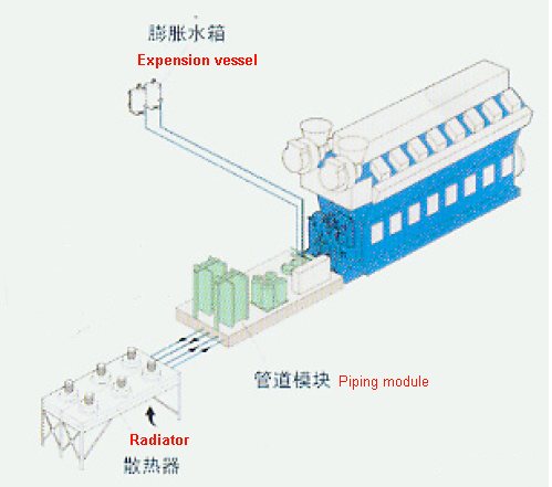
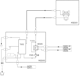
Figure 3: The diagram of coolant system
|
Coolant system, divided into two-closed circulation system, the low temperature water circulation system and high temperature water circulation system connect the atmosphere with the expansion radiator. Excepted from cooling the main machine, it needs to guarantee the proper temperature of the engine to meet combustion demand different load. The low temperature water is responsible for cooling supercharge Air II and lube oil, while the high temperature water for cooling cylinder jacket, supercharge Air I and cylinder head. And the external cooling uses the radiator not adding water.
The low temperature water circulation system and high temperature water circulation system include expansion radiator, water pump, radiator and temperature control valve.
7.4.1 Expansion radiator-----------------------------
Expansion radiator compensates the heat expansion of high temperature water system and high temperature water circulation system which has the effect for compensating water and releasing air.
High temperature expansion radiator-----------------------------250 L
7.4.2Water pump
Both high temperature water pump and low temperature water pump are all centrifugal water pump, driving by the motor, one standby one uses. High & low temperature water pump deliver high temperature water and low temperature water separately through pump, making the circulation in the return line of their own.
High temperature water pump flow-----------------------------108m3/h, 5 bar
Low temperature water pump flow-----------------------------180m3/h, 4.5 bar
7.4.3 Radiator
The low temperature radiator is responsible for cooling supercharge Air II &lube oil and drop off the heat of nozzle, while the high temperature radiator for cooling cylinder jacket, supercharge Air I and cylinder head.
High temperature heat release-----------------------------3020 kW
Low temperature heat release-----------------------------2495kW
7.4.4Temperature control valve
The main function of high temperature water temperature control valve is to keep the constant temperature of out-let high temperature water, while the low temperature water temperature control valve is to keep the constant temperature of in-let low temperature water.
High temperature water temperature control valve …��?.90�?/DIV>
Low temperature water temperature control valve…�…�..decided by the local conditions
Cool the nozzle as burning the heavy fuel oil.
|
Figure4: Nozzle cooling circulation system
|
Heat exchange-----------------------------35kW
Water flow-----------------------------3.2 m3/h�?.0bar
Parallel connection with the main high temperature coolant water system, this unit preheats the cooled water in sets and pipe to guarantee the rapid starting and sudden load of engine. Generally, high temperature coolant water system and lube oil system are preheated with the same module
Preheating temperature-----------------------------40 �?/DIV>
The main function of cooling water supply system is to supply and storage cooling water to meet the water consumption of boiler system, guarantee the normal operation, has the function of softening and dealing with raw water. The cooling water supply system includes softening equipment, radiator and centrifugal water pump.
Systematic radiator…�…�…�…�…�.20 m3
Water supply pump-----------------------------6m3/h, 3 bar (one standby one uses)
Water softening equipment
|
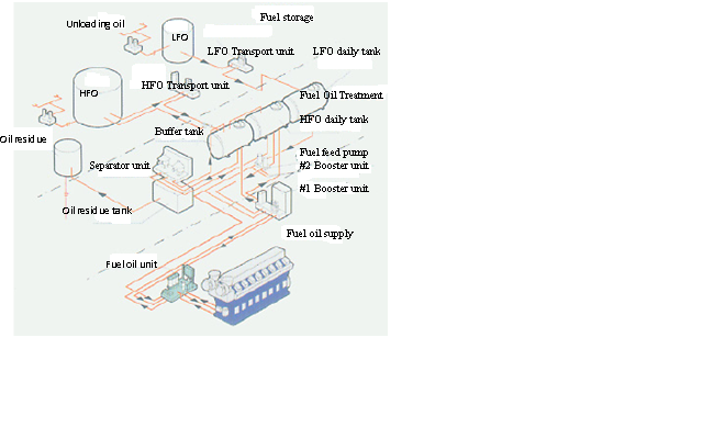
Figure 5: The diagram of fuel system |
Fuel system includes the parts of unloading oil, storage, delivery, handling, supply and gather of return oil, whose functions are to supply fuel continually to diesel and to preserve the constant flow, pressure, cleanness and viscosity. The heavy fuel oil system has the light oil as standby use, when starting and shutdown changing to light oil supply.
Fuel system includes heavy unloading fuel oil unit, heavy fuel oil storage oil-can, heavy fuel oil delivery unit, heavy fuel oil buffer oil cabinet, heavy fuel oil separating module, daily heavy fuel oil cabinet, fuel , supply module, oil sludge tank, diesel unloading oil unit and daily diesel cabinet.
7.8.1Heavy unloading fuel oil unit-----------------------------
This unit mainly contains unloading oil pump, valve and granular filter. The unloading oil pump is gear type or screw pump that provides heavy fuel oil into storage tank from tanker truck through pump, and drives by motor, one standby one uses.
Unloading oil flow-----------------------------70 m3/h�?bar
7.8.2Heavy fuel oil storage oil-can
Arranged in the oil house, heated by the steam and with the normal operation of power station, the oil level must be between upper limit and bottom limit of working tank.
Capacity of heavy fuel oil storage oil-can-----------------------------5000 m3 heated by the steam
Two oil-cans can make 10 machines use 28 days
7.8.3Heavy fuel oil delivery unit
Heavy fuel oil delivery unit has gear type and screw pump, with the main function of delivering heavy fuel oil from storage oil-can to buffer oil cabinet by pump, which drives by motor, one standby one uses.
Delivery pump flow-----------------------------35m3/h�? bar (one standby one uses)
7.8.4Heavy fuel oil buffer oil cabinet
Arranged in the oil house, heated by the steam and with the normal operation of power station, the oil level must be between upper limit and bottom limit of working tank.
Capacity-----------------------------110 m3 heated by the steam
7.8.5 Heavy fuel oil separating module
This unit, very significant, filtrates the heavy fuel oil with separator, which includes heavy fuel oil delivery pump, heavy fuel oil preheating unit, separator, oil sump and switch control cabinet. The separating impurity is delivered to oil sludge tank by pump.
Effective handling capacity-----------------------------20 m3/h
7.8.6Daily heavy fuel oil cabinet
Arranged in the oil house, heated by the steam and with the normal operation of power station, the oil level must be between upper limit and bottom limit of working tank.
Capacity-----------------------------220 m3
7.8.7Fuel supply module
The main function of this unit is to heat and pressure fuel filtration, to supply the diesel fuel under the circumstance of standard temperature, pressure, viscosity and flow, and to realize the transfer between heavy fuel and light oil. This can change into the light oil between the starting and shutdown. Fuel supply module includes conversion valve of heavy fuel oil and light oil, fuel meter, viscosity control, fuel mixed tank, fuel pressure pump, HFO end heater, fuel cooler, fuel twin filters, and control switch cabinet.
Fuel pressure pump-----------------------------2.7 m 3/h, 8 bar(one standby one uses�?/DIV>
Fuel twin filters-----------------------------34μm
Fuel mixed tank-----------------------------70 L
7.8.8 Oil sludge tank
Oil sludge tank, heated by vapor of sludge tank, is used for storage impurity, oil sludge and oil residue after the heavy fuel oil separated.
Capacity of oil sludge tank-----------------------------5 m3
7.8.9 Diesel unloading oil unit
This unit mainly contains unloading oil pump, valve and granular filter. The unloading oil pump is gear type or screw pump that provides heavy fuel oil into storage tank from tanker truck through pump, and drives by motor, one standby one uses.
Unloading oil flow-----------------------------11.52 m3/h�?bar
7.8.10 Daily diesel cabinet
Arranged in the oil house, playing the role of daily working oil tank and storage diesel, and with the normal operation of power station, the oil level must be between upper limit and bottom limit of working tank. It needs to be heated by the steam in winter
Capacity of daily diesel cabinet-----------------------------100 m3
|
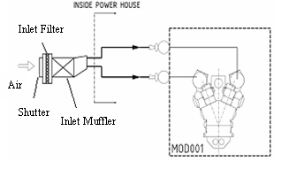
Figure 6: Diagram of inlet system |
Air inlet comes into the cylinder of main machine after turbocharged, to prevent the machine weary and clean air. Muffler is generally installed between turbocharger and air filter, which can reduce the high-frequent noise produced by the turbocharger. The inlet system contains shutter, inlet filter and inlet muffler, which forms the inlet filtration muffler module with each equipment combined.
Air flow-----------------------------30.5 t/h
Inlet muffler-----------------------------30dB (A)
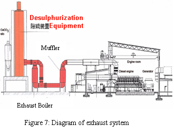
The burned exhaust gas is pushed out by turbocharger, the temperature from 300�?to 335�?depending on the load of engine and used fuel. Before push put exhaust gas, it is recovering waste heat first by the muffler, then by the exhaust boiler. If needed, the second exhaust cleaned system, such as desulphurization equipment, is also installed. The exhaust system includes exhaust muffler, exhaust boiler and desulphurization equipment.
7.10.1 Exhaust muffler
Function: Reduce the exhaust noise of engine.
Exhaust flow-----------------------------66.6 t/h
Exhaust muffler-----------------------------25 dB (A)
7.10.2 Exhaust boiler
Function: Exhaust energy circulation use for heat of heavy fuel oil, water and lubricating oil, heat tracing, containing exhaust muffler, boiler body, air manifold, water pump and control switch cabinet.
Evaporation capacity-----------------------------2.5 t/h
Pressure-----------------------------9 bar
Temperature-----------------------------175�?/DIV>
7.11 Leaked oil & decontamination module
This unit includes fuel leaked oil tank, lube sludge tank, sludge pump and exhaust oil pump, with function for collecting leaked fuel then supplying heavy fuel oil separating module. The lube oil sludge separated by the unit delivers to the oil sludge tank. Also, the oil sludge separated by heavy fuel oil separating module delivers to the oil sludge tank through the leaked oil pump.
Sludge and exhaust oil pump-----------------------------1.8 m3/h�?bar (one standby one use)
Fuel leaked oil tank-----------------------------750 L heated by the steam
Lube sludge tank-----------------------------750 L heated by the steam
Compressed air system mainly contains starting air container, working air container, pressure reducing valve and air compressor.
7.12.11 Starting air container-----------------------------Quantity: 2
Capacity-----------------------------1000 L, 30bar
7.12.2 Working air container-----------------------------Quantity: 1
Capacity-----------------------------500 L, 10bar
7.12.3 Pressure reducing valve-----------------------------Quantity: 2
Capability-----------------------------30-7bar
7.12.4 Air compressor-----------------------------Quantity: 2
Capability-----------------------------30bar, 52 m3/h
7.13 Electrical equipment of generating sets
Medium voltage switchgear mainly includes switch cabinet of generating sets, feeder switch cabinet and BAB Foundation cabinets.
7.13.1 Switch cabinet of generating sets
Cabinet-----------------------------KYN28-12
Dimensions-----------------------------800(W)×1500(D)×2200(H)mm
Breaker-----------------------------VS1circuit breaker 12kV �?30A�?-pole 25kA
Draw out type circuit breaker
Protection-----------------------------PWZB
Quantity-----------------------------10 side
7.13.2 Feeder switch cabinet
Cabinet-----------------------------KYN28-12
Dimensions-----------------------------800(W)×1500(D)×2200(H)mm
Breaker-----------------------------VS1 circuit breaker 12kV�?500A�?-pole 31.5kA
Draw out type circuit breaker
Protection-----------------------------PWZB
Quantity-----------------------------2 side
7.13.3 PT cabinet
Cabinet-----------------------------KYN28-12
Dimensions-----------------------------800(W)×1500(D)×2200(H)mm
Quantity-----------------------------1 side
7.13.4 BAB Foundation cabinets
Dimensions-----------------------------800(W)×1500(D)×2200(H)mm
Color-----------------------------Camel gray
Quantity-----------------------------10side
7.13.5 Power distribution cabinet
Dimensions-----------------------------800(W)×1500(D)×2200(H)mm
Color-----------------------------Camel gray
Quantity-----------------------------3side
7.13.6 Control panel of generating sets
Dimensions-----------------------------800(W) ×800(D) ×2200(H) mm
Color-----------------------------Camel gray
Quantity-----------------------------10 side
Containing control switch, controller, control relay, sensory and alarm display window, etc.
Control function
Engine speed regulator
Digital synchronization & load control
Automatic voltage regulation
Voltage monitoring
Frequency monitoring
Breaker chain
Breaker closing
Breaker tripping
Engine auxiliary module control
Engine starting and shutdown
Alarm display window
Generator control panel displayed the parameter of shutdown and alarm related to electricity and machinery. The parameter of shutdown comes from hard-wired contact end voltage of engine protection system, while the alarm settings is produced by the analog signal from installed sensory according to the main control module. The company can provide different kinds of sensory, such as 4-20mA and PT100.
The displayed alarm & shutdown parameter as follows:
Indicator light of control power supply
Indicator light of engine starting malfunction
Indicator light of emergent shutdown
Engine over-speed indicator light
High engine temperature
High engine oil temperature
Engine coolant level
Low oil pressure
Differential malfunction
Generator over-current
Grounding malfunction
Loss of voltage \ over-voltage
Reverse power
Loss of magnet
High winding temperature
High bearing temperature
High temperature of exhaust pipe
High temperature of exhaust
Low fuel oil level
Low temperature of coolant
Regulator malfunction
Monitor of metal particles in oil pan
Malfunction of lube treatment facility
7.13.7 Direct current cabinet
Dimensions-----------------------------800(W)×600(D)×2200(H) mm
Quantity-----------------------------1 side
AC input voltage-----------------------------AC 400V±15%�?0Hz,three phase four wire system,two input electrical power
DC Output Voltage-----------------------------DC220V�?Working voltage of auxiliary switch cabinet�?/DIV>
Battery capacity-----------------------------Plumbonic acid battery non-maintenance 100Ah
Precision of voltage regulation-----------------------------≤�?.5%
Precision of steady current-----------------------------≤�?.5%
Ripple factor-----------------------------≤�?.5%
System efficiency-----------------------------�?0%
Power factor (PF)-----------------------------�?.92
Operation noise-----------------------------�?0dB
Dielectric strength-----------------------------2000V/min no flashover, no disruption
Grounding resistor-----------------------------�?.1Ω
Output return circuit-----------------------------Standard configuration: KM 5, HM 5.
Cabinet structure-----------------------------Product screen body of our company adopt PK structure, the front with glass doors
Grade of Protection-----------------------------IP30
7.14 Architectural equipment
Architectural equipment includes infrastructure, power plant, pump plant, maintenance workshop, basic equipment, frozen soils construction referred to local environment and detailed construction schedule, subsequently communicated among the buyer, designing institute and the seller.
7. The practicable contents for the contractor
|
No. |
Contents |
Remarks |
|
1 |
The whole design of power station |
Project design satisfied for local environment |
|
2 |
Construction project, equipment foundation construction |
|
|
3 |
Units in place |
|
|
4 |
Installation of power station equipment |
|
|
5 |
Pipes (oil pipe, water pipe, air pipe, smoke pipe, tracing pipe, etc.) |
|
|
6 |
Oil tank& construction |
|
|
7 |
heavy fuel oil, diesel oil, lube unloading oil equipment |
|
|
8 |
Unit station service transformer, generator transformer, electricity transmission |
|
|
9 |
Cable, wire, bridge |
|
|
10 |
250kVA auxiliary machine |
|
9.1.1 The data provided by the seller should be the national legal system of units, ie International System of Units, language be Chinese, the foreign drawings and files of import parts be provided foreign original documents. The seller will provide the whole information and drawing according to units technical specifications, technical requirements, scope of supply and guaranteed conditions.
9.1.2 The drawings offered by the seller should be clear and micro-copied drawings are forbidden to be offered. The organization structure of data is to be clear and strict in logic. The content of data must be correct, accurate, clear and comprehensive, meeting the project.
9.1.3 The seller should provide the data related with the equipment design in time.
9.1.4 If to be found, the seller will provide the files and data free of charge to other data not lined in the contract but project to be needed. When the equipment make an improvement, the seller will provide the new technical data free of charge in time.
9.2.1 Technical files of coordination with project design data and drawings
The seller will provide the data and drawings satisfied for the project design, project installation and operation maintenance.
As shown below:
|
No. |
Designation |
Qty. |
Submission time |
Remarks |
|
1 |
Unit profile, unit installation system drawing, drawings of external auxiliary equipment and connection dimension, installation drawing |
1 |
In one half a month after contract signing |
AUTOCAD
E-document |
|
2 |
The basic reference diagram of generating sets |
1 |
In one half a month after contract signing |
AUTOCAD E-document |
|
3 |
Reference diagram of power plant |
1 |
In one half a month after contract signing |
AUTOCAD E-document |
|
4 |
Principle diagram of system electricity, switch cabinet (one or two return circuit, chain, signal return circuit and external contacts ) |
1 |
In one half a month after contract signing |
AUTOCAD E-document |
|
5 |
Switch cabinet, outlet cabinet installation and connecting diagram |
1 |
In one half a month after contract signing |
AUTOCAD E-document |
9.2.2 The technical files as data and diagram delivered with equipment
The seller shall provide the needed data and diagram satisfied for the project installation, pre-commissioning, performance acceptance and operation maintenance in time (rather than the following files).
|
No. |
Designation |
Qty. |
Submission time |
Remarks |
|
1 |
Drawings of unit profile, external auxiliary equipment and connection dimension, installation drawing |
One set per set |
Delivered with the equipment |
|
|
2 |
Principle diagram of system electricity, switch cabinet (one or two return circuit, chain, signal return circuit and external contacts ) |
|
3 |
Diagram of units control system |
|
4 |
Diagram of external auxiliary equipment control system |
|
5 |
Switch cabinet, outlet cabinet installation and connecting diagram |
|
6 |
Installation operating instructions |
|
7 |
Operating instructions |
|
8 |
Maintenance instructions |
|
9 |
Atlas of spare parts |
|
10 |
List of spare parts about operation maintenance and loss |
|
11 |
List of equipment packing |
|
12 |
certification by manufacturer |
|
OUR PRODUCER |
Scheduled plan of HFO power station project |
No.�?/B>ZGZD |
|
Edition\ modification�?/B>2009/ 0 |
|
Effective date�?/B> |
|
No. |
Period of time
Project name |
20XX |
�?0XX+1�?/DIV> |
|
Jan |
Feb |
Mar |
Apr |
May |
Jun |
Jul |
Aug |
Sep |
Oct |
Nov |
Dec |
Jan |
Feb |
Mar |
Apr |
May |
Jun |
Jul |
|
1 |
Contract signing |
-----------�?/DIV> |
|
|
|
|
|
|
|
|
|
|
|
|
|
|
|
|
|
|
2 |
Engine scheduling |
|
|
---------------------------------------------------------------------------�? |
|
|
|
|
|
|
|
|
3 |
Purchase of generator and auxiliary equipment |
|
|
--------------------------------------------------------------------------�?/DIV> |
|
|
|
|
|
|
|
|
4 |
Unit production and test delivery |
|
|
|
|
|
|
|
|
|
|
|
|
-----�?/DIV> |
|
|
|
|
|
|
5 |
Delivery of unit and auxiliary equipment |
|
|
|
|
|
|
|
|
|
|
|
|
|
--------------------�?/DIV> |
|
|
|
|
6 |
Equipment installation |
|
|
|
|
|
|
|
|
|
|
|
|
|
|
|
---------�?/DIV> |
|
|
|
7 |
System debug |
|
|
|
|
|
|
|
|
|
|
|
|
|
|
|
|
----------�?/DIV> |
|
|
8 |
Operation training |
|
|
|
|
|
|
|
|
|
|
|
|
|
|
|
|
|
|
-�? |
|
|
|
|
|
|
|
|
|
|
|
|
|
|
|
|
|
|
|
|
|
|
|
11.1 Delivery requirements
The buyer is responsible for delivering the equipment and insurance for transportation expenses.
11.2 Package requirements
The seller is in charge of equipment package, the package costs included in the total amount. The package and delivery be in accordance with the specifications of GB191-73 pictorial markings for handling of packages.
11.3 Place of delivery
Place of delivery in the seller’s factory, the buyer should recognize the dispatch goods with the seller helping to provide truck loading.
11.4 If the damage and loss happen to the equipment in transportation, the seller will negotiate with the carrier and claim for compensation.
12.1 Warranty period
Warranty period under scope of supply is one year. In the warranty period, the second party is in charge of free, for the problem of building in quality produced by the defects in equipment manufacture. After the warranty period, the seller provides the technical consultation free of charge and the spare parts at the best price, also responsible for the life-long maintenance.
12.2 Guarantee of field service
In the warranty period, the seller could provide more timely and comprehensive service guarantee. The spot service engineers sent by OUR PRODUCER are for the after-sales guaranteed work and train the spot operation workers, with food and accommodation provided by the buyer.
12.3 Technical training----to provide the training service free of charge
The seller can provide the training of five days for ten persons, with food and accommodation provided by the buyer.
12.4 Installation of on-site guidance and commissioning
The seller is responsible for the installation of equipment and commissioning; while the buyer is for solve the just requirements of the spot service engineers in order to ensure all tasks are carried.
12.5 Commitment
12.5.1 The aptitudes for spot service engineers of the seller as follows:
a、Compliance with law, each rules and regulations on site.
b、In place on time with strong enterprise and responsibility.
c、Knowing about the equipment design in contract, familiar with the structure, having the spot working experience of the same or similar unit, able to do the spot guidance work correctly.
d�?Healthy for the condition of field work.
12.5.2 The responsibilities of the spot service workers
a、The tasks mainly include the processing about problems of equipment quality, guidance for installation and commissioning, participation in trial running and acceptance functional test.
b、Before installation and commissioning, the technical workers should speak clearly to the buyer, explained and demonstrate the procedures and methods to be going.
c、The service workers have the right to dealing with all the problems of technology and business, ie, the service workers have to resolve the problems within the time allowed by the buyer, if the quality problems happen. If the seller entrusts the buyer resolve the problem, the spot service workers of seller must have the power of attorney and afford the related economic responsibility.
d、Pre-negotiation to the buyer about the normal come& go and change of the spot service workers.
12.5.3 The obligations about the buyer
Coordination with the works of the spot service workers and provision with the convenience for life, transport and telecommunications.
The buyer evaluates and recognizes the writing reasonable suggestions, and if the bad result happens for no execution of the buyer, it’s for buyer's account.
Both parties will agree in the contract execution stage about the plan, time, place, and contents of contacts |
|
|