3.12.1 Turbine control module (TCM):
The TCM provides a fully integrated controller for all gas turbine packages; it is based on the Allen-Bradley ControlLogixTM platform. The TCM collect all parameters of the whole package; include gas turbine, generator and other auxiliary system. The TCM transfer these parameters to HMI convenient for operator operate or monitor the package. The TCM provide:
Gas turbine start, stop, speed control and power control during generating electricity.
Lube oil system control
Gas turbine vibration Monitoring
Fire and gas protection
The other auxiliary system control
Package alarm, emergency stop control
3.12.2 Generator control panel (GCP):
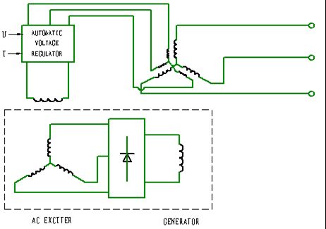
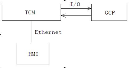
The GCP is a unit provides generating electricity control; it collects parameters of generator, include voltage, current, power, frequency etc. The GCP show these parameters by electric instrument, and transfer these parameters to TCM ,and display these parameters on HMI. The GCP realizes synchronization and excitation adjust of generator. The GCP and TCM transfer signal one another by I/O. The GCP provide:
Generator electricity parameter measure
Synchronization control
Excitation control
3.12. 3 Human machine interface (HMI):
HMI provide friendly human machine interface. HMI is one PC, HMI monitoring software is industry configuration software, include main window, alarm window, trend window etc. . In HMI can display all measure, running state parameter. It looks more concentrative, friendly, beautiful than instrument interface. At the same time it will provide history data saving. HMI and TCM communicate by Ethernet.
3.12.4 Measure system:
The measure parameters of the package include electricity and non-electricity parameter. The non-electricity parameter including temperature, pressure, vibration, liquid level, rotates speed etc., which is measured by sensors. The electricity parameter including voltage, current, power etc., which is measured by electricity isolation transducer .
3.13 Motor Control Center
The motor control center (abbr: MCC) has one distribution cabinet, providing power for all AC motors of pump, heaters, TCM, instruments.
Main AC Electrical Load Specification
|
NO. |
Description |
Rated |
Notes |
|
1 |
Auxiliary Lub Oil Pump Motor |
11kW 380V 50Hz |
DOL starter |
|
2 |
Air Blast Lub Oil Cooler Fan |
15kW 380V 50Hz |
DOL starter |
|
3 |
GT Enclosure Vent Fan NO.1 |
7.5kW 380V 50Hz |
DOL starter |
|
4 |
GT Enclosure Vent Fan NO.2 |
7.5kW 380V 50Hz |
DOL starter |
|
5 |
Lub Oil tank Heater |
4.5kW 380V 50Hz |
Contactor Feeder |
|
6 |
24V DC Battery Charger Supply |
32A 380V 50Hz |
Breaker Feeder |
|
7 |
Anti-condensation Heater Supply for Generator |
2kW 380V 50Hz |
Contactor Feeder |
|
8 |
AC Igniter |
0.177kW 220V 50Hz |
Contactor Feeder |
|
9 |
Turbine Enclosure Lighting |
0.3kW 220V 50Hz |
Breaker Feeder |
|
10 |
Air Filer Control Box Supply |
4kW 220V 50Hz |
Breaker Feeder |
|
11 |
GENERATOR CONTROL PANEL Supply |
16A 220V 50Hz |
Breaker Feeder |
|
12 |
Starter Motor |
90kW 380V 50Hz |
200kW VSD Feeder |
|
|
|
|
|
3.14 DC Power Supply
It provide 24VDC control power supply for the unit and lub emergency power. 24VDC power supply of three engines is provided by one DC cubicle in which charge module and a group of batteries are installed.
4. Instrument air provide system
Instrument air provide system supply the compress air with pressure 0.69Mpa,flow more than 10m3/min( when power station consists of three QDR70 gas turbine generator set )for the whole power station.
The air goes through helical-screw compressor, then compressed air sent to drier in order to get rid of water , oil and other impurity. Finally goes through the filter , air tank send to the connection of every package.
5. Heat recovery steam generator (HRSG)
The heat recovery steam generator can recover the heat in the high temperature exhaust gas of the gas turbine by guiding it into HRSG to generate superheated steam which is used to plant heating process. It consists of six parts: the superheater, the evaporator, the economizer, the steam drum, the deaerating evaporator and the deaerating drum.
5.1 The design parameter of the system: detailedly in the following blank (the gas turbine uses the gas to flame)
|
No |
Name |
Unit |
Value |
|
1 |
Boiler Type: |
|
Horizontal nofired single pressure natural circulation HRSG |
|
2 |
Model: |
|
EGS13-1.5/240-NSV |
|
3 |
Rated Steam Flow for One
HRSG Boiler |
t/h |
13 |
|
4 |
Rated Superheated Steam Press. |
MPa |
1.50 |
|
5 |
Rated Superheated Steam Temp |
°C |
240 |
|
6 |
Make-up Water Temp. |
°C |
20 |
|
7 |
HRSG Boiler Resistance |
kPa |
�?2.0 |
|
8 |
Disposal Mode |
|
in the open air |
|
9 |
Boiler Dimension |
mm |
15240×5910×10000 |
|
10 |
HRSG Boiler Weight (Full of Water) |
kg |
200000 |
|
11 |
Gas Type |
|
Exhaust Gas from Gas Turbine |
|
12 |
Exhaust Gas Flow |
kg/s |
29.32 |
|
13 |
Exhaust Gas Temp. |
°C |
468 |
|
14 |
Max. Temperature of exhaust gas |
°C |
�?00 |
|
15 |
Exhaust Gas Temp. for HRSG Boiler Design Condition |
°C |
468 |
|
16 |
Outlet Temp. of HRSG Boiler |
°C |
�?30 |
|
17 |
The allowed resistance of HRSG |
kPa |
�?.0 |
5.2 Technical process
5.2.1 Gas flow of HRSG: High-temperature gas flow discharged from the gas turbine shall flow through a high-temperature T switching gate of which one channel shall enter into by-pass flue chimney and another channel shall enter into the HRSG boiler.
5.2.2 Steam flow of HRSG: the desalted water from chemical treatment chamber will be the making up water of HRSG. The making up water shall be sent to the deaerating drum by the pump supplied by the owner. And the pressure of the making up water before into HRSG must be more than and equal to 0.3MPa(g).
Deoxidized water in deaerating drum shall be sent to economizer by frequency conversion feed water pump, where it shall be heated and then sent to steam drum. After further heated through natural circulation between steam drum and evaporator of HRSG, steam-water mixture shall be generated, and then make separation into steam drum. The saturated separating water shall go on circulation and saturating steam shall be sent to the superheater of HRSG where superheated steam shall be produced for supplying.
5.2.3 Major pipe of steam adopts a single manifold. All superheated steam generated by superheater of HRSG is guided into one manifold toward steam supplying. There shall be discharging valve on the main steam pipe.
5.2.4 Water consumed by boiler is fed by water treatment chamber.
5.3 Applicable Standards and codes
The following standards and codes are applied in the HRSG system:
ASME SECTION 1 2004
Technical Supervision Regulation for Safety of Steam Boiler
Strength Calculation of Pressure Parts for Watertube Boiler GB9222-88
The certification according to the Module G (EC unit verification) of Pressure Equipment Dtrective PED97/23/EC for 10 sets HRSG shall be provided
6. Environment Protection
6.1 Applicable standard and criterion
Can refer to the power plant local or both sides agreed standard and criterion.
6.2 The influence of package on environment
When the QDR70 gas turbine co-generation package runs, it will influence of ambience with noise, exhaust gas, waste water, waste oil etc..
6.3 Environment protect measures
6.3.1 Noise
The main noise source of the gas turbine generation power plant is the gas turbine engine, below measures are taken for the gas turbine to control the noise:
Gas turbine engine is installed a separate sealed enclosure with sound insulation and absorption to prevent gas turbine noise transmitting outside directly;
On all airflow channels of the gas turbine engine enclosure are install silencers;
All conduits connecting to gas turbine engine adopt soft connection to prevent vibration delivering;
Gas turbine acoustic must be airproof including gate, window, hole, connection of acoustic and base;
Base of gas turbine generator sets adopt to segregate vibration;
The type of other auxiliary equipment require low noise ,for example fan, pump .
By the means mentioned above, the noise and vibration of gas turbine power station is better the noise level is not more than 85dB(A).
6.3.2 Waste Gas
After natural gas is burned ,waste gas contents :CO2, H2O, O2 and SO2, NOX etc, CO2, H2O, O2 is no nocuous gas, SO2, NOX is nocuous gas.
The output of NOX less than 25ppm,because we adtop DLE technology of Siemens.
The sulfide quantity in natural gas effect the exhaust concentration of SO2.The exhaust concentration of SO2 can meet the drain requirement by controlling the sulfide quantity in natural gas
6.3.3 Waste water
The wast water of the gas turbine generation power plant include the recovery boiler and washing of turbine . The blow down of every waste heat recovery boiler is about 0.7t/h,the temperature is 200°C, Because water has been purified through a series of processing before feeding into the boiler, there is no need to add any medication while the unit runs. At first the sewage drains in the sinkhole for cooling, and then drains in barrel-drain of the power plant. The washing water can drain into the tank. Buyer can reclaims waste water from tank period of time.
6.3.4 waste oil
There is a little waste oil in normal operation and service of the gas turbine generator set. The buyer takes the responsibility for reclaiming waste oil.
6.3.5 Station virescence
The virescence has especial effect of depollution and improve environment. It can adjust temperature, clean the dust, purify atmosphere, reduce noise. Develop virescence of power station when build the power station, grow the tree of the feat growth side of the way, lay green fencing and shrub under the conduit, grow greensward and flower around the workshop.
7. Appendix:
Drawings
Note of drawings
Appendix 1: the gas turbine generator P&I drawing
Appendix 2: the gas turbine generator layout drawing
Appendix 3: the lubricating system P&I drawing
Appendix 4: the fuel system P&I drawing
Appendix 5: the frie&extinguss hant P&I drawing
Appendix 6: the instrument air provide system P&I drawing
Appendix 7: the MV single line drawing
Appendix 8: the low voltage distributing MCC drawing
Appendix 9: the DC system drawing
Appendix 10: the HRSG boiler P&I drawing
Appendix 11: the shape drawing of the HRSG boiler
Appendix 12: the three sets vertical layout drawing
Appendix 13: the three sets parallel layout drawing