|
Power plant operates an 40 MW Dual Fuel based, DG Power Plant which is intended to supply power in merchant sale to the desired customers based on load requirements.
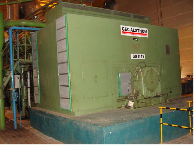
The Plant has four sets of Sulzer France make and 16 ZAV 40 S type Diesel Engines of capacity 10.56 MW each incorporated with latest PLC based condition monitoring and equipment protection system along with SCADA.GEC ALSTHOM make alternators are coupled with each DG sets and power is generated at 11 kV voltage level on the generator terminals. This is further stepped up to 110 kV by single 56 MVA Transformer and evacuated by the Power Transmission lines.
a. Diesel Generator Set (DG Set)
Power Plant consists of four units each of 10.56 MW DG sets. The Diesel Engines manufactured by Sulzer France in Year 1991, the engine 16 ZAV 40S is designed for burning LDO / HSD or HFO. However, sets running on Heavy Fuel Oil (HFO) sets, distillate such as Light Diesel Oil (LDO) or High Speed Diesel (HSD) oil is used during starting & stopping of the engines.
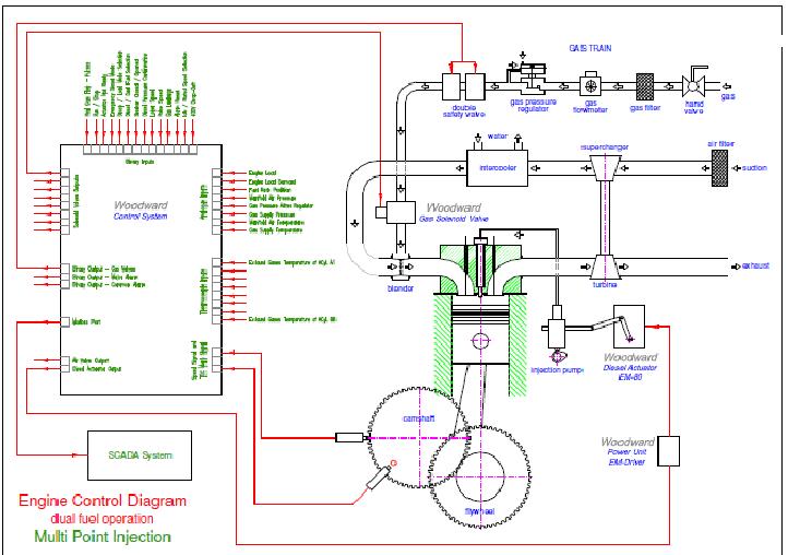
These four DG sets then converted for Dual Fuel (DF) Operations in October 2011 to January 2012 so as to reduce carbon emissions & generating cost. With the conversion sets are now operated on Natural Gas as a main fuel & HFO or LDO or HSD as a pilot fuel. Solenoid Operated Gas Admission Valves (SOGAV) and Woodward governing system is in use for the safety in Gas operations. Average ratio of Gas & Oil at efficient and safe operation to run the sets is about 60 to 65% Gas & 35 to 40% HFO or 70 to 75% Gas and 30 to 25% HSD.
Each Diesel Engine is equipped with two numbers of ABB make VTR 454-11 Turbochargers.
Complete strip down Overhaul of all Four Diesel Engines & Turbochargers has been done in 2010-2011. During Strip down overhaul major components like Cylinder liners, 3 nos of Turbocharger rotors, Pump elements, Nozzles, Valves, etc were renewed. Post overhaul Sets have run for about 300 t 400 hours.
Entire DG house is treated with acoustic panel in order to reduce the noise level. This acoustic system has been commissioned in Feb 2011.
 |
b. Fuel oil system:
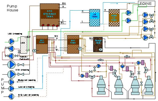
The maximum requirement of fuel oil is 3 tonnes / hour in DF mode and 10 tonnes / hour in Liquid fuel mode. One main HFO storage tank equipped with three nos. of electrical suction heaters provides storage capacity of 480 m3. Electrical suction heaters maintain the temperature of HFO and no electrical heat tracer & insulation is considered for the main HFO tank.
HFO from road tankers is unloaded by 2 nos (1W +1S) HFO unloading pumps each of 30 m3 /hr capacity and is led to the main HFO storage tank. From the main storage tank HFO is transferred to settling tank (of 120 m3 capacity). The settling tank is insulated & provided with electrical heat tracer. HFO transfer pumps each (1W+1S) of 20 m3 / hr capacity are used for transferring oil from main HFO tank to settling tank. HFO from settling tank is fed to the Separators (Alfa Laval MOPX 310) for the purification & clarification. Clean fuel coming from separators is stored in Day tank (of 120 m3 capacity).
c. Fuel oil Sludge handling system:
The Sludge generated in the Fuel oil Treatment (FOT) room during Fuel oil treatment, leak off, and lube oil separators is collected in a bulk Sludge storage tank of 20 m3 capacity. Sludge from the tank can be loaded in Tankers through sludge loading pump of 10 m3 / hr capacity to dispose off.
d. Lube oil system ďż˝?Receipt, storage, pumps, separators etc.
Lube oil from road tankers is unloaded by 1 No lube oil unloading pump of 10 m3 /hr capacity and led to the Lube oil storage tank of 20 m3 capacity. Transfer of Lube oil from the lube oil storage tanks to Engine lube oil system tank (Dry sump) is transferred by oil transfer pumps.
Used Lube oil from the engine system tank can be transferred by used oil transfer pump to used lube oil storage tank of 20 m3 capacity. The transfer of used lube oil from used lube oil storage tank to tankers for disposing is used by lube oil loading pump of 10 m3 /hr capacity.
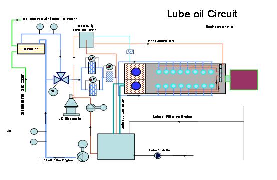
The lubricating oil System, consist of the dry sump arrangement with the separate LO tank for cylinder lubrication and the Bearing lubrication. Bearing lubrication done by electrically driven pumps. Cylinder lubrication done by the engine mounted hydraulic pump driven by the pressurized bearing lube oil, in case of emergency done by hand driven pumps mounted on the engine.
e. Air Conditioning & Ventilation System
The control room and PLC panel (local control room) is air conditioned. The control room and PLC panel room temperature is maintained at 24o C.
The dry ventilation of DG building is provided with Supply and Exhaust air fans. The purpose of ventilation system is to remove heat load generated by DG & its auxiliaries in side DG house in order to maintain DG house floor level temperature.
Two nos. Centrifugal supply air fans along with ventilation room at 8.0 meter EL above control room are installed and ducting is provided for distribution of ventilation air on alternator side. The capacity of each fan is 1.25 lakh m3 /hr. 8 Nos of vane axial fans (wall mounted) at 5.65 meter EL on roof of auxiliary bay provides ventilation air at engine side, each of 0.5 m3 / hr capacity. For exhausting the hot air from the DG room Exhaust air fans are provided at the auxiliary side of Engine room.
All other buildings such as DG auxiliary room, MCC room, FOT room are provided with Supply air fans.
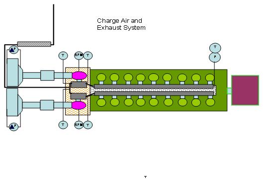
f. Charge Air and exhaust gas system
AAF makes oil bath suction air filters are installed in suction line of turbochargers. Acoustic silencers are installed at the AAF filters; all the charge air coolers are brand new in the charge air system (installed in 2011). SOGAV valves are installed on the charge air bend just before the Cylinder head for natural gas injection. The structurally supported stack are consists of 4 independent uninsulated flues each of 4 meter diameter and 85 meter in height. Exhaust gas silencer are installed in the exhaust gas system.
g. Station air system
For the instrument air consumption 1 no of instrument air compressor is available connected with Instrument air receiver of 500 L capacity. This instrument air is used for thermostatic valve operations, operations of engine mounted solenoid valves and for separators operations.
h. Start up air system
To meet the starting air requirements of the four DG sets 4 numbers of starting air compressors are available along with its accessories such as individual air bottles for engines, distribution piping, etc. Each starting air bottle is having a capacity of 2600 L and safe working pressure of 30 kg/ sq.cm. In addition to the starting air bottle is engine is equipped with 2 nos of safety air receivers having capacity of 15 L and working pressures of 7 bar & 30 bar.
2 nos of starting air compressors are Hatlapa make (L80) & 2 numbers are Ingersoll Rand (15T2) overhauled in July 2011.
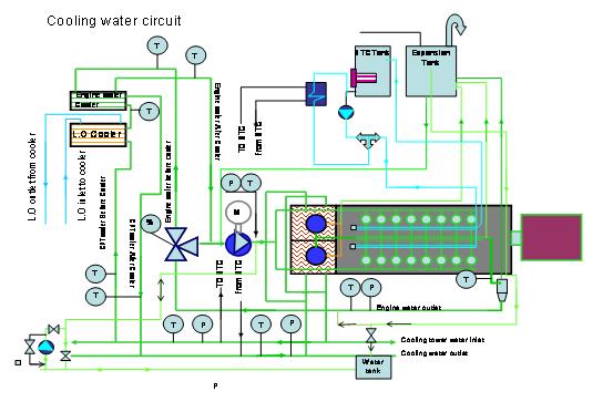
i. Cooling Water System:
Cooling water system including raw water and make up water pumps, CWT, CWP, PHE, blow down and treatment system
Raw Water System
The source of raw water for the plant is from line. The water is tapped from the pipe line with 150 NB pipe line with adequate pressure of 5 bars. The water is stored in the Fire and raw water reservoir compartment No.1 & 2 and will also have has reserve storage for fire fighting. The partially underground raw water reservoir has capacity of 1300 m3of storage. As the MIDC water at 5 bar pressure is available on 24 hours time cycle, line taps are connected to the cooling tower make up, fire fighting system, drinking water, domestic water, etc. Also the reservoir water can be taken into any of the system through pumps.
Cooling Water System A recirculation type cooling system with induced draft tower of Paharpur make is facilitating the cooling of Engine jacket water. The induced draft cooling towers (IDCT) have two cells each of 800 m3/hr capacity and are of treated wood construction with PVC film type fill.
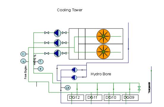
This also consist of three cooling tower Recirculation Pumps in which 1+1 running and 1 will be standby these pumps supplies cooling water for 4 DG sets and auxiliaries. Very low level in sump pump trips cooling water circulation pump .Cooling tower make up pump to stop at high level and start at low level in pump sump.
The cooling tower is designed for atmospheric wet bulb temperature of 28o C. Cold water temperature of 32o C and cooling range of 16o C.
The 16 ZAV 40S engines are water cooled by three different systems.
1. Jacket water cooling system
2. Fuel valves water cooling system Raw water system
j. Water Softener Plant
Soft water plant of 500 LPH fulfils the requirement of soft water for for the LO oil and FO separators for the centrifuging purpose, and engine cooling water, turbocharger washing. Storage tank for soft water of 10 m3 capacity is installed on terrace of DG room. Hydrophore unit is connected to tank outlet line for keeping the water pressure constant for various auxiliary requirements in the range of 4 to 6 bars.
k. Fire hydrant system
Following systems are used for control/extinguish in case of fire in plant.
i. Fire Hydrant system for all areas of the plant.
ii. High velocity water sprays system (Emulsifier) for 56 MVA generator power transformers.
iii. Portable fire extinguishers.
iv. Fire Detector system comprises of
a. Smoke & flame detectors
b. Gas leak detectors
c. Fire detection cum alarm control panel.
l. Over head cranes
EOT crane of 5 ton capacity having one girder and two numbers of hoists each 5 ton and having independent pendants is available in Engine room for material handling inside the DG house. (1 hoist of 5 ton is Swift make & commissioned in Feb 2012).
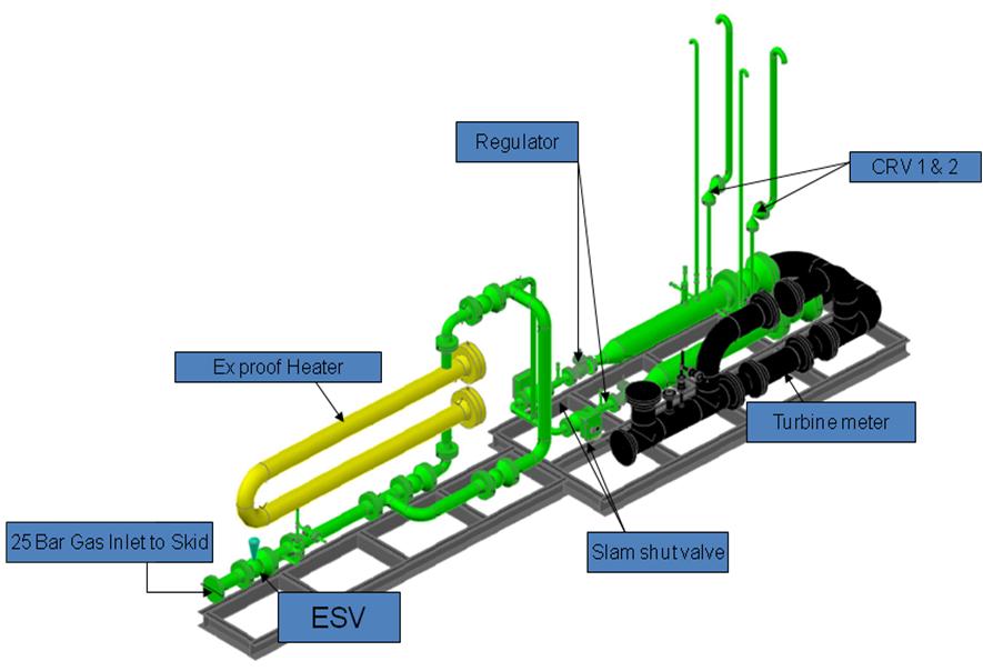
m. Natural Gas System
A 4’� gas line coming from GAIL gas skid is connected to Power gas skid with insulating joint. Power Natural Gas Pressure Reduction & Heating skid reduces the 25 bar Gas pressure to 4 bar in downstream line as required by the Engines and heat the natural gas to the required temperature of 15 to 20o C. Heating of natural gas helps in preventing the condensation and entering of moisture in the electrical control valves, this prevents the malfunction of electrical equipments.
NG pressure reduction Skid:
Make: Emerson Process Management
Inlet pipe ďż˝?4ďż˝?# 300 Outlet Pipe ďż˝?8ďż˝?# 150
Inlet Pressure: 23 -25 barg Outlet pressure: 3 to 4 barg
Flow rate: 0.022 to 0.22 MMSCMD Outlet temp.: 15 to 20o C Heater: Thuba Swiss make (3 banks total 100 kW)
Generator is GEC Alsthom make with rating 11KV,12800KVA,0.8 Pf,50 HZ, 500 RPM and Rated Current of 671.8 A. This AC generator is driven by diesel engine, air cooled, in open-circuit with suction in basement and discharge in room. Rotation of the Generator is anti-clock wise when seen from back to the engine. The generator rotor is supported with Pedestal type bearing. The main coupling on diesel side is of the rigid type. The generator is designed for stress less than elastic limits of metal at over speed of 120%.
Stator cage is consisting of special low magnetic loss silicon steel sheet segments.
The copper stator winding and stator is Insulated various insulators like Epoxy resins, Mica Tape, Glass fabrics, carbon tape etc which is results in insulation Class F and Temperature rise class B
Rotor the forged steel shaft is provided with coupling plate at Mfg. the rotor hub is made of thick plates tightly bound to the shaft No. key is mounted.
Damper cage is made of 4 copper bars located in each pole shoe.
Rotating Diode exciter The exciter is mounted opposite the coupling under the generator casing between the auxiliary generator PMG and the rotating rectifier assembly. The rotating part are installed on the shaft. The coiled stator is secured to a common PMG bearing support. The rotating rectifier assembly is secured to the magnetic circuit of the rotor and is provided with a 6-
Diode Graetz bridge with a in-parallel voltage limiter on each diode.
Auxiliaries Generator (PMG) The PMG is mounted close to a bearing under the generator casing the rotating parts are installed on the shaft. The coiled stator is secured to a common support between the exciter and the bearing.
Rotor Earthing It is intended to fix the path of currents possibly induced in the rotor and to protect the shaft line.
The Generator Exciter is of RK 90-20 type having diode assembly and the exciter and AVR system which regulates the voltage of the generator in running system in Automatic and Manual mode.
Bearing with Oil flow The bearing is bolted to a support to which PMG and the exciter stators are also secured. The bearing is made of cast iron and is provided with fins for natural cooling>It is also fitted with indicator for oil level monitoring. The bearing oil is circulated by the small oil Pump with motor of rating 0.37 Kw 1500 rpm motor. The inlet to this pump is connected from bottom of bearing housing and outlet to of Pump to the top side of baring housing.
b.Main Control Room ďż˝?Control and Monitoring system
OCW panel is connected with 11 KV OAK, engine control system New CMR PLC panels and New Governor panels for engine control and regulation and synchronizing.OCW panels consist of Protective relays (Old relay replaced with New numerical type replay make Woodward Model-MRA4 only for Generator protection for Generator breaker), Auxiliary Transformer feeder, and Power Transformer feeder. All engines common alarms system for including auxiliaries and New CMR PLC panel at Local control room is in connection with OCW panels and SCADA for engine starting/stopping system for synchronizing purpose Automatic Synch Relays using units synchronizing by selection for both manual and auto by Woodward, Model SPM D.Each engine is controlled for Load sharing control by governor panel and excitation control by PLC and AVR GEC Alsthom.
OCW auxiliary supply voltage is of 110 VDC which is supplied by the 110 V DC battery chargers.
Engine Details:
No. of Engines : Four
Serial Number of Engines : 740099, 740100,740101,740102
Engine Make : New Sulzer Diesel, France
Engine Type : 16 ZAV 40S
(16 denotes Nos. of cylinder and 40 denotes Cylinder bore in centimeter)
Engine Speed : 500 rpm
Governor : Woodword In ďż˝?pulse II Governor and EM 80 actuator.
Engine Fuel Oil : HFO (Heavy Fuel Oil) / GAS
Engine Capacity : 10.56 MW
Cylinder Arrangements : V- Form 50 Deg.
Cylinder Bore : 400 mm
Piston Stroke : 560 mm
Swept Volume : 70.4 Lt
Fuel Injection Pressure : 400 bar
|

