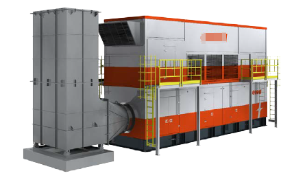
| TECHNICAL SPECIFICATION OF SKID MOUNTED GAS TURBINE GENERATOR 1.0 INTRODUCTION • This gas turbine genset is mainly consist of three skids: the main skid\ filtration and ventilation skid and exhaust. • The main skid contains enclosure, gas turbine, gearbox, electric starting system, gas fuel system, lubrication system, water wash system, electric generator, fire suppression system, electric system and control system. • The filtration skid is mainly consisted of the filters and silencers for the combustion air and enclosure cooling air. • The gas turbine genset features quick installation and movement, the estimated rig up time is less than one week. • The gas turbine genset and parts are new and unused. TYPICAL ONLY

• Design environment is per Table 1 Table 1. Ambient Environment No. | Description | Data | 1 | Altitude | <1,000 m | 2 | Max. Ambient Temperature | 35 °C | 3 | Min. Ambient Temperature | 0°C |
l The GTG is equipped with enclosures with fire alarm system and aerosol fire suppression system. The enclosures also provide sound attenuation, dust control and weatherproofing of equipment. l Main parameters of the gas turbine genset are as follows: Table 2. Main Parameters
Item | Description | Gas Turbine ISO Base Rating / ISO Working Condition (1) | SGT A-05 KB7HE G/W(Natural Gas Fuel Only) 5.8 MW, Gas Fuel without water (Dry) | Heat Rate, LHV (Btu/kWh) | 10,241, Gas Fuel, Dry | Heat Rate, LHV (kJ/kWh) | 10,796, Gas Fuel, Dry | Generator | LEROY SOMER | Terminal Voltage | 10.50 kV ± 5% | Frequency & Speed | 50 Hz, 1,500 rev/m in | Electric Power Output | 5.3MW (2)(3)(4), Gas Fuel, Dry | Noise Level | Average value >85 dBA at 1 meter | Skid Overall Dimensions (mm) | Main Skid: �?12,000x3,000x3,000 (Lx W x H) Filtration Skid: �?12,000x3,000x3,400(Lx W x H) Exhaust: �?4500x3,000x6,500 (Lx W x H) | Max Total Mass (kg) | �? 70,000 |
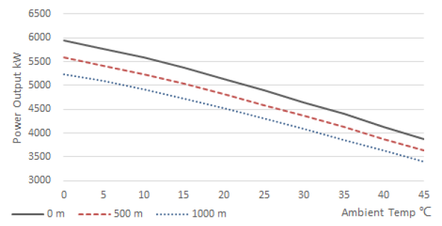
Note 1: The International Organization for Standardization (ISO) has defined the following standard conditions for rating and comparing gas turbine engines: Ambient Temperature - 15°C Barometric Pressure -101.3 kPa Relative Humidity - 60% Inlet and Exhaust Losses - None Emission Controls - None Fuel - Gas per requirements of Annex 1 Note 2: Electric Power Output Condition: Inlet Temperature - 15°C Altitude - Sea Level Inlet pressure loss - 140 mm w.g Exhaust pressure loss - 115 mm w.g. Relative Humidity - 60% Bleed Air Extraction - 0 kg / sec Fuel - Gas fuel per requirements of Annex 1 Power factor - 0.8 Note 3: As the actual working temperature, altitude (barometric pressure), humidity, etc. are likely to be inconsistent with ISO conditions,actual guaranteed power generation of the generator set may vary from ISO calculation results. Fig 1 is reference of package Power Output. (CT output temperature shall be kept below 1057 °C and the max electric power output shall be no more than 6000 kW.) Fig 1 Package Power Output SGT-A05 KB7HE Engine (kWe) 
3.0 CODES AND STANDARDS The design specification, manufacturing process and technical quality refer to the following standards (if applicable): Table 3 Design Specification and Standard Standard | Description | GB 755 | Rotating electrical machines-Rating and performance | GB/T 1029 | Test procedures for three-phase synchronous machines | ISO-12944 | Paints and varnishes —� Corrosion protection of steel structures by protective paint systems | GB/T 32821 | Gas turbine applications-Safety | GB 50316 | Design code for industrial metallic piping | NFPA 2010 | Standard for Fixed Areosol Fire-Extinguishing Systems |
Standard | Description | IEC 60265-1 | High-voltage switches - Part 1: Switches for rated voltages above 1 kV and less than 52 kV | IEC 60298 | A.C. metal-enclosed switchgear and controlgear for rated voltages above 1 kV and up to and including 52 kV |
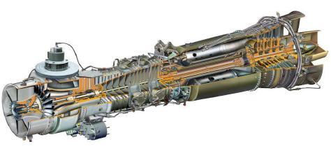
2.0 ENCLOSURE Enclosure will be divided into different compartment, and is provided with sections of drive chain and electrical systems. The enclosure is well sealed and includes functions of noise reduction, dust control and weatherproofing. The electric cabin will be equipped with air conditioner for the temperature regulation. 3.0 FILTRATION The filtration for combustion air and ventilation air is designed in one skid, which mainly includes: • Combustion Air inlet filter & silencer • Enclosure Ventilation Air inlet filter • Enclosure Ventilation Air fans 4.0 GAS TURBINE The proposed gas turbine is the SGT-A05 KB7HE G/W natural gas fueled gas turbine. However, the unit is designed to be adaptable for SGT-A05 KB7S. Table 4 Gas Turbine Main Parameters ISO Shaft Power | 5,880 kW | Rated Speed | 14,530 rpm | Efficiency | �?32% | Fuel | Gas Fuel Only | Emission | NOx �?300 mg/Nm3 |
TYPICAL ONLY 
5.0 GEARBOX Planetary gearbox is integrated with PTO for starter and lubrication pump. An overrunning clutch is equipped in the gearbox. Table 5 Gearbox Main Parameters Rated Power Input | 5,880 kW | Rated Speed Input | 14,530 rpm | Rated Speed Output | 1,500 rpm | Efficiency | �?/span> 98% |
6.0 ELECTRIC STARTING SYSTEM The gas turbine electric starting system includes one electric starting motor and a remote VFD installed in the electric cabin. The electric starting motor is for engine starting, water wash and purging. 7.0 EXHAUST SYSTEM The exhaust system is designed in one skid, and it mainly includes one set of diffuser and one elbow with silencer, which is for exhaust gas as well as noise reduction. 8.0 GAS FUEL SYSTEM Fuel system is gas fuel only type, and dual fuel function is optional. Most supplied gas fuel components have been placed in the turbine enclosure. For Warranty and operational reliability, the design and use of gas turbine and related gas fuel system components must meet the requirements of Annex 1. Table 6 Gas fuel system requirements No. | Item | Requirements | 1 | Composition | To be confirmed with Annex 1 | 2 | Heat Value(reference) | LHV: 904 BTU/scf | 3 | Consumption | 1337 kg/h (ISO working condition, Dry) | 4 | Pressure | 1897 ±3 4 kPa | 5 | Temperature | At least 11 °C higher than dew point, <93 °C | 6 | Wobbe Index | 1170 ±130 | 7 | Filtration Accuracy | 3 microns maximum | 8 | Other requirements to gas supply equipment (not included in this package) | Sintered metal filter not allowed | Stainless steel piping after last filter | Auto shutoff function at fuel inlet - Customer supplied | Flow rate measurement function - Customer supplied | Bleed function at fuel inlet - Customer supplied |
Table 7 Gas Fuel System Configuration No. | Item | Qty. | Description | 1 | Simplex Gas Filter | 1 | This unit is designed to remove particulates with a limited ability to “knockout�? liquids. Due to space limitations, the unit is not designed for liquids coalescing. Fuel should meet the fuel requirements when CNG and LNG are used as fuel. Excessive liquids or contaminants should be removed by customer prior to supply to the particulate filter. | 2 | Manual shut-off valve | 1 |
| 3 | Fuel Shutoff Valve | 2 | Vent function integrated | 4 | Fuel Metering Valve | 1 | For flow rate regulation | 5 | Instrumentation | / | As Required | 6 | Piping / Tubing | / | As Required |
9.0 LUBRICATION SYSTEM The main lubrication system is designed to supply sufficient lubrication to gas turbine, gearbox and generator. Table 8 Key Components of Lubrication System
No. | Item | Qty. | Description | 1 | Oil Tank | 1 | About 700L | 2 | Duplex Filter | 1 |
| 3 | Cooler | 1 | Air cooling | 4 | Pre-lube pump | 1 | AC motor driven | 5 | Main lube pump | 1 |
| 6 | Piping and Valves | 1 |
| 7 | Oil demister | 1 |
| 8 | Flame Arrester | 1 |
| 9 | Instruments and Sensors | / | Subject to the final design |
Note! Mobile Jet Oil 387 is recommended. Usage of other oils shall be approved by the manufacturer. 10.0 WATER WASH SYSTEM The water wash system serves to clean the gas turbine compressor. The gas turbine and package will be provided with offline water wash connections only. The off-skid wash piping and equipment (pumps, water tanks, etc.) are optional. Deposits on the compressor will reduce air flow, compressor efficiency, and compressor pressure ratio. Compressor cleaning will remove dirt deposits and restore the performance. It should be noted that once serious contamination happens, full power may not be restored. Regular cleaning of the compressor will help maintain performance. Compressor cleaning can also slow down the corrosion process, thereby prolonging the life of the blades and reducing the corrosion product deposition. The cleaning interval of the gas turbine needs to be determined according to the gas turbine usage and must be confirmed with maker. Water quality and cleaning agents which are used to wash the turbine should be approved by maker and per the SIEMENS O&M Manual. 11.0 ELECTRIC GENERATOR Primary output voltage rating of this synchronous generator is 10.5 kV 50Hz. Table 9 Generator Parameters Rated Speed | 1,500rpm | Insulation Grade | H/F | Capacity@104 °F | 6,300 [email protected] kV | Efficiency | �?96% @100% load, 0.8 power factor | Frequency | 50 Hz | Voltage | 10.5 kV | Rated Power Factor | 0.8 | Cooling Type | IC01 |
12.0 FIRE SUPPRESSION SYSTEM Functions of Aerosol Fire Suppression System are as follows: • Combustible gas content detection and alarm in gas turbine compartment • Fire detection and alarm in turbine compartment and Power Control Module. • 30 seconds after fire detection, the Aerosol will release automatically. • Aerosol release can be locked out manually during maintenance. • In case of fire, dampers will close in ventilation systems. Table 10 key components of Fire Suppression System No. | Item | Qty. | 1 | Aerosol fire extinguisher | As Required | 2 | Combustible gas detector | 2 | 3 | Turbine enclosure thermal spot detector | 2 | 4 | Audible and visual alarm | 2 | 5 | Manual switch | 2 | 6 | Manual stop switch (LOTO Switch) | 1 | 7 | Fire suppression control system panel (FPP) | 1 | 8 | Fire damper | As Required |
13.0 ELECTRIC SYSTEM The electrical system includes the following systems: generator Medium Voltage (MV) system, generator excitation system, low-voltage (LV) auxiliary power distribution, UPS system, generator relay protection system, cable routing / tray system, lighting system, lightning protection, grounding system, air conditioning system, fire suppression etc. 13.1 Overall Electrical System The gas turbine generator set’s electrical system and generator are designed for a rated voltage of 10.5 kV and 6,300 kVA/ 0.8 PF. The generated power is sent to external equipment through the generator circuit breaker. The power for the Unit Auxiliary Transformer is from generator breaker load side. The UAT provides low-voltage power for the unit. 13.2 Neutral Grounding in Electrical System The generator uses High-Resistance Neutral Grounding. The 380V system is a three-phase four-wire system grounded by TN-C. 13.3 Selection of Main Electrical Equipment The excitation system for the generator is brushless with a fixed 12kV medium voltage switchgear with metal enclosure, and vacuum type circuit breaker. The UAT is dry-type. The low-voltage power distribution cabinet is a fixed type panel. The components in the low-voltage switchgear are from premium brands / suppliers, and the low-voltage power inlet circuit breakers used are frame circuit breakers with excellent protection functions and reliable quality. For small-capacity switches, circuit breakers with thermal and magnetic protection are used. The electrical secondary system adopts relay protection device, which is incorporated into the gas turbine unit control system together with the control of the generator. 13.4 Power Supply and Motor Secondary System 1) AC power distribution system The low-voltage auxiliary power grade is 380 V/220 V, and the transformer feeds the auxiliary equipment in the package. The starting power of the unit comes from a separate black start diesel generator. After the unit is started, the auxiliary system is supplied with power through an auxiliary transformer. The electrical equipment in the package is directly distributed by the low- voltage power distribution cabinet located in the electrical cabin. 2) UPS system The output power supply of the UPS inverter is the normal power supply of the AC nonstop power bus. The UPS cabinet includes MCC main inlet circuit breaker, controller, control power supply circuit, operating power supply circuit, etc. The AC uninterruptible power supply system provides adjustable sinusoidal AC voltage for important loads under normal and accident conditions. 3) Motor secondary system The starting motor is regulated by variable frequency device regulation; other motors are operated by Direct On Line (DOL) motor starters. The gas turbine control system monitors the motor's operating signal, the power switch opening and closing status signals. 13.5 Excitation System 1) Selection of generator excitation mode The excitation system for the generator is brushless. 2) Functional configuration of generator excitation system The excitation device adopts microcomputer control, and the adjustment can support the control of multiple operation modes on constant terminal voltage and constant generator power factor. Setting the remote-control point of the excitation switch when the generator is normally shut down or accidentally tripped, the excitation switch will be tripped to stop the excitation of the generator. When the excitation system of the generator fails and the excitation switch trips, the main switch of the generator is combined to activate the generator loss-of-excitation protection. 3) Composition of excitation system The excitation system is composed of permanent magnetic generator, AC exciter and excitation device. The excitation device controls the excitation voltage and current of the generator by judging the generator voltage and current signals. 13.6 Relay Protection Device The electrical secondary system adopts a microcomputer integrated protection device. The generator protection device and excitation device are integrated into the panel. The metering Watt-Hour meter is also installed in this panel. 13.7 Arrangement of Electrical Equipment The 12 kV generator outlet circuit breaker cabinet, generator neutral grounding cabinet, low-voltage power distribution cabinet, generator protection control panel, and the Unit Auxiliary Transformer are installed in the Power Control Module (PCM). The generator outlet current transformer, outlet voltage transformer, and bus-bar voltage transformer are installed in the generator outlet circuit breaker cabinet, and the generator neutral grounding transformer is installed in the generator neutral grounding cabinet. 13.8 Lighting System The power supply voltage of the lighting system is 220 VAC, and the lighting is powered by a 380V/220V transformer or UPS in the power control module. High-illuminance and energy-saving LED lights are selected for this unit. 13.9 Lightning Protection and Grounding System The metal roof of the skid is used as the air-termination device, and the main beams are used as the general equipotential grounding boards, which are connected to the main grounding-electrode network. Grounding includes work, protection, and lightning protection shared grounding devices, and all electrical equipment, conductors, pipelines, generators, etc. are grounded in accordance with regulations (Code for design of AC electrical installations earthing). 13.10 Cable Routing and fire-proof sealing system The cable in the package is laid in the metal cable tray along the monocoque, with minor portions of rigid and flexible metal conduit. Tight sealing treatments have been adopted during the cable installation process. The outdoor cable tray adopts fully enclosed metal structure to provide effective protection. 13.11 Air-Conditioning System The electric cabin mounted air-conditioning system is designed to guarantee the electrical equipment can work normally in the specified temperatures and humidity. 14.0 CONTROL SYSTEM It mainly consists of the gas turbine control system, MCC auxiliary control system, generator control system and power supply system. The functions are as follows: Gas turbine control system is mainly used for controlling the gas turbine running and instruments. The gas turbine control system serves to regulate the fuel supply according to load change and monitor and control the combustion temperature exhaust temperature, intake temperature, oil pressure and speed. The instrument control serves to monitor and control the related instruments such as the intake pressure, lube oil pressure, filtration pressure, lube oil temperature, cabin temperature, bearing temperature, gas turbine vibration, gearbox vibration and generator vibration to guarantee the safe and stable running. MCC auxiliary control system serves to control and monitor the electric devices such as the start motor, pre-lubrication motor, oil-mist separator, air fan, cooler fan, heater, light, etc. The generator control system with comprehensive protection serves to control the generator voltage to ensure correct and stable voltage, frequency and power, including the voltage regulator, controller, switch cabinet, etc. The operation interface is designed and developed by us independently, which can be customized and modified according to user's requirements. The functions are as follows: Control the start/stop of gas turbine; Monitor the running data of gas turbine, generator (voltage, current, frequency, power factor, and voltage, frequency and current of bus bar) and sensors; View and deal with the alarm data in Alarm Interface Shift between manual and automatic control in Manual Interface.
|

