| 2.3 8L27/38主要零部件介�?/span>Main parts of 8L27/38 2.3.1 机体Crankcase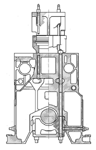 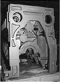
�?/span>1:主要零�?/span>/连接螺栓/未加工的机体 Figure�?/span>Main components/Tie rods/ Crankcase in unmachined condition 发动机机体是由铸铁制成的。它为整体式结构并且具有足够刚度。贯穿螺栓从倒挂式主轴承盖下边缘延伸到曲轴箱顶部的边缘,缸盖螺栓从缸盖的上边缘延伸至机身中部,同样的横拉螺栓使主轴承盖横向压紧在机体上�控制驱动和减振器均并入机体中�?/span> The crankcase of the engine is made of cast iron. It is one-piece and very rigid. Tie rods extend from the lower edge of the suspended main bearing up to the top edge of the crankcase and from the top edge of the cylinder head to the intermediate floor. The bearing caps of the crankshaft bearings are also laterally braced with the casing. The control drive and vibration damper housing are integrated in the crankcase. 2.3.2 曲轴Crankshaft曲轴由特殊钢锻�而成,�挂式安装,每缸有两个平衡块,通过高强度螺栓平衡振动质量�凸轮轴传动装置的齿轮由两半块组成,并由切向布置的4个螺栓紧固�通过螺栓将其连接到曲轴上的定位轴承法兰上�?/span> The crankshaft is forged from special steel. It is arranged in a suspended 27/38ner and has 2 balance weights per cylinder held by extension bolts for further balancing of the oscillating masses. The drive gear for the gear drive consists of 2 segments. They are held together by 4 tangentially arranged bolts. The connection to the locating bearing flange is by head bolts 2.3.3连杆Connecting rod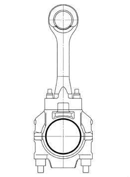
连杆的设计采用所谓的船用大头连杆设计方案。当起吊活塞时大端轴承不需��拆开。这种设计有利于安全操作(不会改变位置,不用重新调整)�该设计方案降低了活塞吊装高度�?/span> The structure of the connecting rod is made up of the so-called marine head arrangement. The joint gap is above the connecting rod bearing. When retracting the piston the connecting rod bearing need not be split. This has advantages for operational safety (no change in location / no new matching), and this type of structure reduces the piston removal headroom. 2.3.4活塞Piston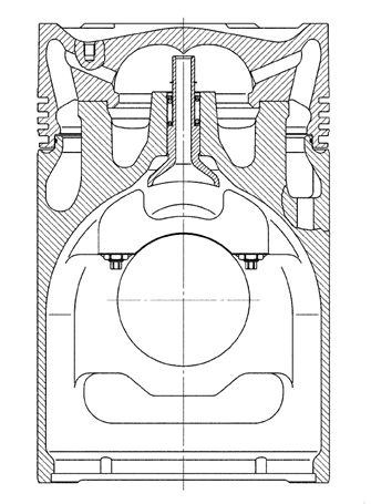
活塞由活塞顶部和活塞裙部两个基本部分组成,活塞裙部材料为球墨铸铁,活塞顶部材料为高强度锻钢�选择这种材料和结构设计可以有效承受高的爆发压力,并允许窄的活塞间隙�窄的活塞见此同阶梯式活塞设计一��,可减少活塞环上的机械负载,防止磨损颗粒进入,避免油膜参与燃烧� Basically, the piston consists of two parts. The skirt is made from spheroidal grey cast iron. The piston crown is forged from high-quality materials. Mate- rial selection and design effect high resistance levels to the ignition pres-sures that arise and permit tight piston clearances. Tight piston tolerances and the structure of the piston as a stepped piston reduce the mechanical loading on the piston rings, restrict the access of small particles and protect the oil film from combustion gases. 2.3.5涡轮增压�?/span>Turbocharger涡轮增压器安装在发动机的右上角,采用NR系列增压器,即具有径流式压气机和径流式涡轮的增压器(NR26~34)� 此系列增压器的主要特点是不用冷却,独立涡轮进气和排气壳体。这种结构可以确保: 涡轮既有足够可利用的排气能量;部分负荷是降到露点以下不会产生腐蚀�?/span> The turbocharger is generally mounted on the coupling side on engines which provide the drive for propeller installations, and on the counter cou- pling side on engines which drive generators. The turbocharger is mounted at right angles to the engine. Turbochargers from the NR series are used,i.e. turbochargers with radial compressors and radial turbines (NR26 - NR34).The special characteristic of this range is the non-cooled and insulated tur- bine inlet and outlet housing. This structural system ensures,that the turbine has the full exhaust energy available and that no corrosion caused by falling below the dew point under part load is to be expected. 2.3.6两级中冷�?/span>Two-stage intercooler两级中冷器代替单级中冷器。安装位置相同�二级负荷运行参数中冷器主要用于为了保证有效利用热量,另一方面,�过切断第2级中冷可改善低负荷运行参数,即提高增压空气温度� Charge air cooler two-stage instead of single-stage. The arrangement is in the same fitting space. Two-stage charge air coolers are primarily used, in order to guarantee effective heat utilisation On the other hand, the operating values can be improved in low-load operation by switching-off stage II, i.e. by increasing the charge air temperature. 2.3.7喷油定时调节装置Fuel injection timing control device改变喷油定时使点火提前或滞后的设备�在工作转速内,此设备使点火压力提高到设计值,从�明显降低燃油消�率�相反,向“滞后�方向调节导致点火压力下降因�降低NOx排放�?/span> Facility for changing the fuel injection timing to "ignition advance" or "retard". In the area of service work, the device enables the ignition pressure to be increased to the design value, thereby obtaining a significant reduction in the fuel consumption. On the other hand, an adjustment in the direction "retard" combined with a drop in ignition pressure results in a reduction in the nitrogen oxide emission. 通过轴上的一个螺旋齿轮,喷射凸轮轴可相对起始位置转动。轴向移动的螺旋轴套在液压活塞作用下实现这个动作。�过内部控制活塞,液压活塞无级依次到达适当位置�?/span> The injection camshaft can be turned relatively compared with the starting position by means of a helical gearing on the shaft. This takes place by means of an axially movable helical bush, which is moved by a hydraulic piston. In turn, the hydraulic piston is brought steplessly to the requisite position via an internal pilot piston. 2.3.8油雾探测�?/span>Oil mist detector轴承损坏、活塞卡滞以及燃烧室漏气会加剧油雾形成�油雾探测器监测曲轴箱内的油雾浓度或空气浑浊度。抽吸泵不断将曲轴箱各处空气吸出,分离大油滴后�至装有红外过滤器的测量系统�外部二极管发出对应于亮度的电信号,并传�至监测单元中�?/span> Bearing damage, piston seizing and blow-by from the combustion chamber give rise to increased formation of oil mist. The oil mist detector monitors the oil mist concentration or air opacity inside the crankcase. An aspirator pump continually draws air from all sections of the crankcase. After remov- ing large drops of oil, it is fed to a measuring system with infrared filters. The diodes located at the outlet supply an electrical signal corresponding to the amount of light received to the monitoring unit. 2.4燃油系统Fuel system喷油泵�过较短的连接管与分配管连接�在高压作用下燃油经过高压油管输�到喷油器。喷油泵靠凸轮轴的凸轮驱动� The injection pumps are connected to the distributor pipe by short lengths of line arranged on the side opposite the exhaust. They convey the fuel under high pressure through the injector pipe to the injection valves . The injection pumps are actuated by cams on the camshaft. 当压力超过弹簧弹力时,喷油器针阀打开喷油孔横截面。当泵柱塞的螺旋控制槽到达吸入孔时,喷油循环结束。由控制油量调节套和燃油齿条作用旋转泵柱塞来调节燃油喷油量�喷油时刻由凸轮轴的凸轮的相对位置决定�?/span> The injection valve needle opens the cross section to the injection holes when the pressure building up has exceeded the spring force. The injection process ends when the inclined metering ramp of the pump plunger reaches the suction hole. The amount of fuel to be injected is influenced by the rota- tion of the pump plunger by the control sleeve and control linkage. The injection timing depends on the relative position of the cams on the camshaft. 燃油系统示意图:Fuel System figure: 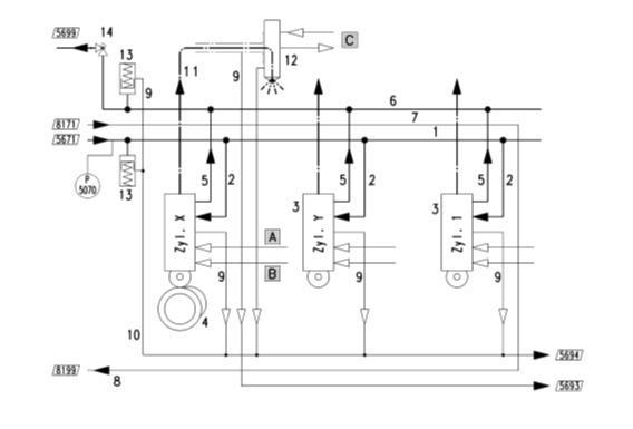
2.5润滑系统Lube system 8L 27/38发动机润滑系统是由外部预供油泵�自净滤器、分离机等设备和机带润滑油泵一��构成的润滑系统�发动机和增压器的内部润滑是强制润滑�缸套的润滑由发动机上的润滑系统供给独立的系统供给。对于每台发动机,都需��有独立的润滑系统�?/span> 8L 27/38 engine lubrication system is a lubrication system composed of external pre - supply oil pump, self - purification filter, separator and other equipment and lubrication oil pump together with engine. The internal lubrication of the engine and supercharger is forced lubrication. The lubrication of cylinder liner is supplied by the lubrication system on the engine. For each engine, there is a need for an independent lubrication system. 滑油系统包含:预供油泵�加热器�温度调节阀�压力调节阀�机油冷却器�机油自净滤器、机油泵、机油粗滤器、润滑油分离系统和油箱构成� The lubrication oil system includes: pre - supply oil pump, heater, temperature control valve, pressure regulating valve, oil cooler, oil purification filter, oil pump, oil filter, lubricating oil separation system and lubrication oil tank�?/span> 流程图如下:The flowchart is as follows�?/span> 
2.6冷却系统Cooling system发动机用水分低温水系统�高温水系统,高温水�低温水系统分别独立闭式循环控制,通过卧式散热器进行冷却� The engine water mainly contains low temperature water system and high temperature water system�?/span>high temperature water and low temperature water system are respectively independent closed cycle control, and cooling through the horizontal radiator. 高温水管路主要设有膨胀��箱�预热器�备用泵�过滤器�冷却器,三�高温调节阀� High temperature water pipe road is mainly equipped with expansion water tank, preheater, standby pump, filter, cooler, three - way high temperature control valve. 低温水管路主要设有膨胀��箱�备用泵�过滤器�冷却器,三�低温调节阀� The low temperature water pipe road mainly includes expansion water tank, standby pump, filter, cooler, three - way low temperature regulating valve. 高温水系统�低温水系统膨胀��箱采用钢板制作,焊接光洁无渗漏,水箱用钢架支撑�箱盖板设计便于清洗;全部管口均为法兰接口;水箱设通气孔�出水管�补水管�溢流管�排污管�膨胀水管,每个水箱补水管前设有补液阀��每个水箱设水位上下限控制和液位指示;主管路进水应配备过滤器,管道和阀进行防腐处理,管路采用无缝钢管,焊接采用氩弧焊� The expansion tank of high temperature water system and low temperature water system is made of steel plate, and the welding is smooth and no leakage, and the water tank is supported by steel frame. The design of the cover plate is convenient for cleaning; All nozzles are flanged; The water tank shall be equipped with vent hole, outlet pipe, water supply pipe, overflow pipe, drain pipe and expansion water pipe, and the fluid replacement valve shall be provided before each water filling pipe of each water tank, and the upper and lower limit control and liquid level indication shall be provided for each water tank; The incoming water shall be equipped with filters, pipelines and valves for anti-corrosion treatment, and the pipeline shall adopt seamless steel pipe, and argon arc welding shall be used for welding. 冷却系统流程图片如下�?/span>The cooling system flow picture is as follows�?/span> 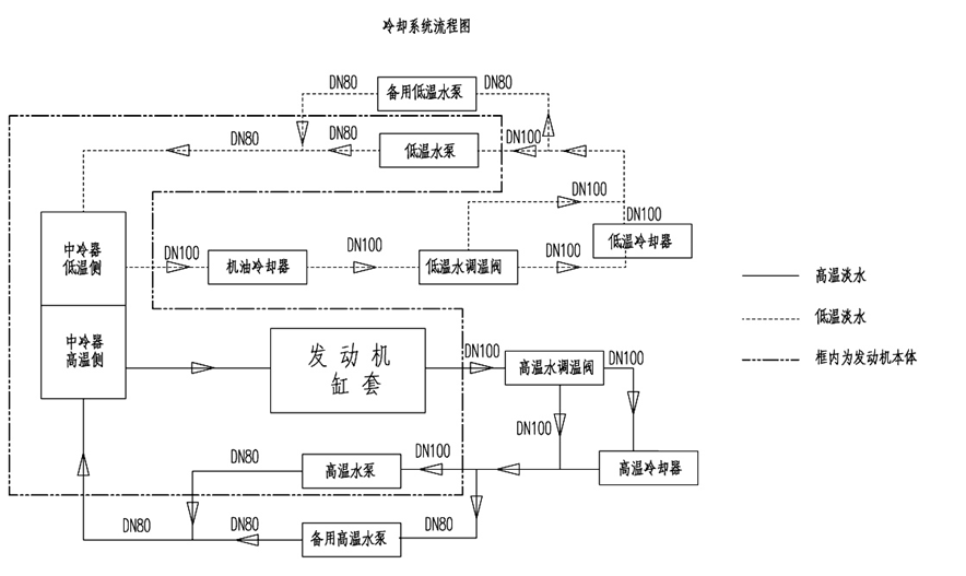
2.7排气系统Exhaust system发动机采用废气涡轮增压装置,排气系统将燃烧后排出的废气引入增压器涡轮机中,以充分利用排出废气的余能� The engine uses the exhaust gas turbine booster, and the exhaust system introduces the combustion exhaust gas into the turbocharger turbine to make full use of the residual energy of the exhaust gas. 每两个相邻的气缸与一组排气管相连,每组排气管通过波纹管连接在一���?/span> Each two adjacent cylinders are connected to a set of exhaust pipes, each of which is connected by a bellows. 气缸内燃烧后排出的废气,经每组排气管进入增压器涡轮机中,利用排出废气的余能,驱动增压器工作,最��从排气�管排出� The exhaust gas discharged after combustion in the cylinder, through each set of exhaust pipes into the turbocharger turbine, uses the residual energy of the exhaust gas to drive the turbocharger work and finally discharge from the exhaust 27/38ifold. 排气总管出口处设有连接法兰,是供用户安装排气引管和消音器用�排气总管应采用外接波纹管和消音器或排气管相连,这样可控制振动应力�?/span> The exhaust gas discharged after combustion in the cylinder, through each set of exhaust pipes into the turbocharger turbine, uses the residual energy of the exhaust gas to drive the turbocharger work and finally discharge from the exhaust 27/38ifold�?/span> 排气的背压(出气总管的废气与大气之间的压力差)不得超�?kPa�?/span> The back pressure of the exhaust gas ( the pressure difference between the exhaust gas of the outlet 27/38ifold and the atmosphere ) shall not exceed 3 kPa. 2.8启动系统Starting system采用压缩空气启动Starting with compressed air 8L 27/38柴油发电机组采用压缩空气启动最��空气压力�?0bar,设备见列表�?/span> 8L 27/38 generating set adopts the compressed air to start the maximum air pressure of 30 bar, and the equipment is listed in the list: 设备名称 Equipment Name | 型号 Model | 数量 Qty | 其他 Others | 空气高压全无油空压机 High air pressure, no oil air compressor | WWW-1.2/30 | 1 | 3MPa | 高压空气�?/span> High - pressure air bottle | A0.5-3(CB76493-1997) | 1 |
| 空气管路(不锈钢包括调压阀�� Air line ( stainless steel, including pressure regulating valve ) |
| 1 |
|
共设1个高压储气瓶,�台全无油高压空气压缩机�减压阀�安全阀�压力表�管道组成空气启动系统。空气压缩机最��压力�?.5MPa。保证连续启�?次� There is a high-pressure air bottle, a high air pressure, no oil air compressor, pressure relief valve, safety valve, pressure gauge, pipeline air start-up system. The maximum pressure of air compressor is 3.5 MPa. Guarantee to start up continuously 6 times 启动系统照片如下�?/span>Starting system photos are as follows�?/span> 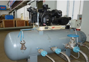 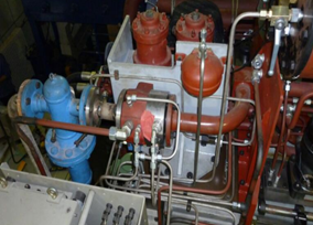
|

