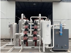
| 9. Molecular sieve purification system (1) Equipped with a device for uniform distribution of airflow, which has long service life, saves investment and reduces energy consumption; (2) Design and calculate according to GB150 "Steel Pressure Vessel", and use the method of stress analysis to calculate the fatigue strength; (3) The switching butterfly valve with new sealing structure has good reliability; (4) A built-in powder filter is used at the outlet to effectively prevent dust from entering the cold box and ensure the long-term stable operation of the air separation plant.
Manufacturer | Nuzhuo | Type | Vertical bunk bed; Auto control | Air dealing capacity | 600Nm³/h | Air working pressure | 1.0Mpa(G) | Air inlet temperature | 10�?/span> | Air outlet temperature | 16�?/span> | Molecular sieve regeneration temperature | 170�?/span> | Single cylinder adsorption cycle | 4 hours (Auto switch) | Content in air | CO2 | �?PPm | H2O Dew Point | �?70�?/span> | Qty | 1 set | Single set supply range�?/span> |
| 9.1molecular sieve adsorber | 2 sets | Type | Vertical bunk bed | Molecular sieve | Full dose | Activated aluminium oxide | Full dose | 9.2.Electrical heater | 2 sets�?/span>one for spare�?/span> | Type | Vertical | Design power | �?/span>30kw | Shaft power | �?/span>11kw | 9.3.Oxygen vent silencer | 1 Set | 9.4.Valves and piping accessories | 1 Set | 9.4.Special tool | 1 Set | 9.5.Spare parts | 1 Set | 9.6Random file | 1 Set |
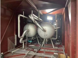
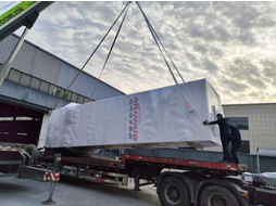
10. Fractionation column (1) Fractionation tower adopts all-aluminum structure sieve tray tower and plate-fin type main heat exchanger and main condensing evaporator, which makes the whole device compact and efficient. (2) The single-column reflux expansion process is adopted, with high rectification efficiency, abundant cooling capacity of the device and stable operation. (3) The oxygen pressure of the product is 0.3MPa (G), which can be directly output for use. (4) The cold box adopts an integral structure, and the inside and outside are treated with anti-corrosion. (5) The advanced performance calculation software imported from abroad is used to optimize the flow of the device, and at the same time, the advanced distillation calculation program is used for calculation to ensure that the system has the best technical and economic indicators. (6) The overall design of the fractionation tower system fully considers the safety, reliability, maintainability and other factors of the equipment. white. The overall design of the cold box system of the fractionation tower is based on safety and reliability, and all pipelines in the cold box are Perform stress analysis and calculation, and use high-strength aluminum alloy material to ensure that the pipeline is not deformed. All vessel holders, valves Door brackets and pipeline brackets have undergone strict strength calculation and cold compensation calculation. The brackets are all structured with thermal insulation pads to reduce heat conduction loss.
Manufacturer | Nuzhuo | Model | FO-50 | Size(Determined at final design) | 2.2m×2.3m×9m | Quantity | 1 set�?/span>whole set�?/span> | Air treating capacity | 50Nm3/h | Oxygen Production | 50m³/h | Oxygen Purity | �?9.6% | Oxygen outlet pressure | 0.3MPa.G |
* Scope of supply for a single set:
No. | Item Name | Qty | Material | Remark | 1 | Main heat exchanger | 1 Set | Al | aluminum plate fin | 2 | Column | 1 Set | Al | sieve-plate tower | 3 | Condensing evaporator | 1 Set | Al | aluminum plate fin | 4 | Subcooler | 1 Set | Al | aluminum plate fin | 5 | Expansion air filter | 2 Pcs | Al |
| 6 | Oxygen/Nitrogen vent muffler | 1 Pc | Q235 |
| 7 | Cold box | 1 Pc | Q235 |
| 8 | Pipe valve in cold box | 1 Set | Al |
| 9 | Cold box external valve | 1 Set | Carbon Steel |
| 10 | Supports for valves, pipes, vessels | 1 Set | Stainless steel | In cold box | 11 | Platform ladder railings, etc | 1 Set | Q235 |
| 12 | Expanded perlite | Full Dose |
| From Henan | 13 | Residual carburetor | 1 Set |
|
|
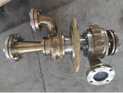
11. Air bearing turbine expansion unit (1) The expander adopts gas bearing turboexpander, the impeller design adopts computer simulation design, and adopts five-axis coordinate CNC milling machine to process, and the efficiency is more than 82%. (2) In order to protect the safe operation of the expander, an alarm interlock function is set in the value, the automatic control system will automatically alarm and stop. Manufacturer | Hangyang; Xida | Type | Gas bearing, fan brake | Model | PLPK-50/0.36-0.025 | Swell capacity | 310Nm³/h | Swell medium | Oxygen-enriched air | Inlet/Outlet pressure | 0.36/0.025MPa(G) | Inlet temperature | 130K | Brake medium | Air | Quantity | 2 Sets (1 for spare) | *Scope of supply of single set�?/span> |
| 1.Expander | 1×2 Sets | 2.Brake fan (assembled with main engine) | 1×2 Sets | 3.Air filter | 1×2 Sets | 4.Air silencer | 1×2 Sets | 5.Spare parts | 1 Set |
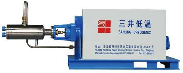
Cryogenic liquid pump | 1 sets | Manufacturer | Sanjin | Model | SBP50-150/150 | Type | Horizontal, piston, electromagnetic speed regulation | Column number | Single | Design temperature | -196�?/span> | Working medium | LO2,LN2,LAR | Max outlet pressure | 0.8 Mpa | Max inlet pressure | 0.02Mpa | Max working pressure | 15Mpa | Design pressure | 16Mpa | Flow | 100-250L/h (Liquid) Adjustable | Motor work rate | 4.0KW | Weight | 450KG | Supply scope | Cold end (pump head) | 1 set | Transmission case | 1 set | Pulley mechanism | 1 set | Foundation | 1 set | Cold end frid | 1 set | YCT | 1 set |
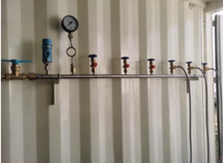
13. Inflatable row Manufacturer | Nuzhuo | Type | 6 filling heads*2 rows | Outlet Pressure | 15 MPa |
14. Supply of electronic control system 14.1. Design principles: 14.1.1. Under the condition that the electronic control system meets the design and process requirements, it must ensure that the equipment can operate safely and reliably, and is easy to operate and maintain. 14.1.2. The setting of control, protection, metering and signaling devices for electrical equipment such as motors shall comply with the relevant national electrical standards or regulations. 14.1.3. In order to improve the reliability of power supply, 14.1.4. The electrical equipment is set up with a control panel next to the machine, on which the necessary electrical meters and signals and operating elements are set. 14.1.5. When the low-voltage motor is started, the voltage drop of the low-voltage bus is less than 15%. 14.2. Buyer provides power 14.2.1. High voltage power supply: 10KV, frequency 50Hz, three-phase three-wire neutral point is not grounded. Low-voltage power supply 380V/220 ± 5% three-phase four-wire neutral point is directly grounded. 14.2.2. DC control power supply: DC220V. 14.2.3. The buyer shall provide the power grid system diagram, short-circuit capacity and single-phase grounding capacitor current value related to the device within one month after the contract takes effect. 14.3. Selection of electrical equipment (specific specifications and quantities are subject to the final design data) 14.3.1 High Voltage Switchgear Type Mid-mounted vacuum switchgear (Comprehensive insurance adopts Zhuhai Malata) Technical parameters 10KV Incoming line cabinet 1 set 1 PT cabinet 1 measuring cabinet Compressor switch cabinet 1 set Water resistance soft start cabinet (modified to solid state soft start cabinet) 1 set (Dayu Electric or Beijing Dali) 1 running cabinet 14.3.2. DC screen Technical parameters DC220V Quantity 1 set (6KVA) 14.3.3 Low-voltage switch cabinet (one main switch, two drawer cabinets) Type Drawer switch cabinet (Schneider components in the cabinet) Technical parameters 380V Quantity 1 set 14.3.4 Control cabinet (box) beside the machine 1 pre-cooling machine (pre-cooling machine factory matching) 14.3.5 1 set of heating furnace power adjustment cabinet 15. Supply of Instrument control system 15.1 Design Principles 1) The instrument control system should be able to effectively monitor the production process of the entire set of air separation equipment, to ensure long-term stable and reliable operation of the equipment, and easy operation and maintenance. 2) Instruments and DCS series systems must be advanced and reliable, and reliability is the main consideration while considering advanced nature. 3) The instrument control system adopts the principle of combining the central control room (PLC), the instrument on the side panel and the local instrument control. All the interlocking (starting interlocking and protection interlocking) and control of the air separation plant are completed in the PLC , to ensure that the entire instrument control system is reliable, advanced, and easy to operate and maintain. 4) The controller of DCS adopts redundant or fault-tolerant controller, power supply and redundancy of communication bus to ensure the reliability of the system. The controller has the function of online modification. 5) In the air separation control room, set the upper computer monitoring and 1 printer to monitor the process parameters of the air separation unit, with functions such as display, operation, memory, report printing and maintenance. 6) Set up a printer in the air separation control room to print reports on the main parameters of the production process and print out the process parameters in the production process, various operation actions of the operator and system failures. 7) When the air separation plant is in normal operation, the display and operation are completed on the PLC. Each main stand-alone machine is set up with instrument cabinets next to the machine, and the functions of the machine side panel are as simple as possible. The need for start-up of stand-alone equipment. 8) All interlocking circuits are designed according to the ISA standard and using the principle of power-loss safety to ensure safe shutdown in the state of power-loss. 9) Set up an online analysis room, the analyzer is installed in the analyzer cabinet (including the pretreatment device) supplied in a complete set, and the process parameters of the online analysis enter the PLC system for display, recording, alarm and other processing, and the analyzers are equipped with 4- 20mA output signal, among which the analyzers involved in the interlocking have "measurement" and "calibration" switches, and the solenoid valve with dry contacts is sent to the central control PLC to avoid artificial interlocking and parking when the instrument is calibrated. Set up manual analysis of valve discs. The analytical sampling valve stand and each online analyzer are centrally installed in the analysis room. 15.2 Instrument selection 1) The PLC system uses Siemens. 2) UPS uninterruptible power supply selects Santak products or Meilan Geran products (6KVA, 30MINS backup battery). 3) The pressure, differential pressure and flow transmitters use Yokogawa intelligent products. 4) The switching valve of the molecular sieve purification system is selected from American VALL or American Bray and the same manufacturers, and the normal temperature control valve and low temperature control valve are selected from Hangyang tooling or Wuxi tooling products. 5) The two-position three-way and two-position five-way solenoid valves are imported products with low power consumption from ASCO, and the brand of the regulating valve positioner is Azbil from Japan. 6) The online analyzer is supplied in complete sets and adopts international first-line brands Analytical instrument (1 set) No | Item Name | Spec. | Qty | Remark | 1 | Oxygen Analyser | 0�?/span>10ppm | 1 Set | Siemens or equivalent |
7) The local instrument indication, the pressure indication on the instrument beside the machine adopts the spring tube pressure gauge. 8) The measuring element adopts platinum thermal resistance with PT100 graduation number, among which the resistance in the cold box adopts double platinum resistance, and the platinum resistance adopts the products of Anhui Tiankang or Shangzi No. 3 Factory. 9) Bimetal thermometer is used for local temperature indication. 10) The gas flow measurement adopts Hangzhou complete set of throttle orifice flowmeter. 15.3 Scope of supply of meter (single set) 15.3.1 Main instruments |
| Pressure transmitter | �?/span>25 Sets | Regulating valve and switching valve | �?/span>20 Sets | Magnetic valve | �?/span>15 Sets | Platinum thermistor | ~13 Pcs | Trace oxygen analyzer | 1 Set | Dew point analyzer | 1 Set | UPS | 1 Set | Pore plate | 3 Sets | 15.3.2 Instrument panel |
| Side cabinet of precooling machine | 1 Set | Analyzer cabinet | 1 Set | Molecular sieve purifier control cabinet | 1 Set |
15.4 DCS system (1 set) Upper computer | 2 Sets�?/span>DELL�?/span> | Configuration: |
| Operating floor | 1 Set | PLC Cabinet | 1 Set | CPU Unit | 1 Pc | Power module�?/span>24V/10A | 1 Pc | Printer | 1 Set | I/O points set aside 15% margin (less than one card for one card) |
15.5 Other instruments Including bimetal thermometer, pressure gauge, three valve group, DC current, etc. 15.6 Information and technical documents Meter list Front layout drawing of side cabinet Electrical schematic diagram, gas circuit diagram, wiring diagram inside the cabinet Instrument control system manual logic diagram I/O point table Alarm value, interlock list 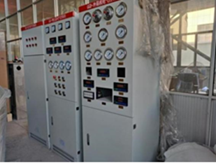 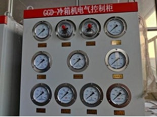
16.Scope of work 16.1 Seller's scope of work 1) The seller is responsible for all equipment design, process design, instrument and electrical control design, engineering design, equipment and accessories supply in the boundary area. 2) The intersection point of the pipeline between the seller and the designer is one meter outside the boundary area. 3) High and low voltage power distribution room and air separation control room are within the scope of engineering design. 4) The seller is responsible for the installation of pressure vessels and pipelines within the boundary. 5) The seller is responsible for the equipment of the local technical supervision department, the supervision and inspection fee of pressure pipeline, and the cost of flaw detection of pressure pipeline. 16.2 Buyer's Scope of Work 1) The user should ensure that the quality of the raw air should comply with the provisions of Chapter 1 2) Design, equipment, materials and construction of public works and civil works, including equipment foundation, workshops and other buildings, lighting, sanitary facilities, water supply and drainage, communication, air conditioning, fire protection, heating and lifting facilities and various types of pre-buried pieces, etc. 3) Materials and construction of lightning protection facilities and grounding devices in the nitrogen production boundary. 4) Connect the high and low voltage power supply to the upper connector of the seller's incoming cabinet. 5) The instrument gas, nitrogen, water and electricity during the mechanical test, linkage debugging and start-up of the device. 6) Geological survey report, safety assessment and environmental impact assessment of civil engineering design. 7) The anchor bolts that need to be embedded in the civil engineering drawings shall be supplied by the buyer. 17. Technical data provided by the seller The seller will submit the technical data to the buyer according to the following scope and time. The technical data submitted by the seller will be provided in three stages: preliminary, final and random. 17.1 Preliminary technical data The seller shall provide the equipment layout drawing and detailed survey layout drawing within two weeks after the contract takes effect. The seller shall provide the preliminary design information required for the project in quadruplicate and electronic version within 30 days after the contract takes effect, content include: 17.1.1 Complete Process Flow Diagram with Control Points 17.1.2 The general drawing of the equipment (including auxiliary machines), the basic drawing, the middlemost drawing with the orientation dimension of the nozzle and the connection form Weight and special fittings (eg bellows, pipe filters) 17.1.3 Reference drawing of equipment layout 17.1.4 List of equipment (listed separately), including name, quantity, model, specification, manufacturer, etc. 17.1.5 List of supporting instruments, including content: model, specification and quantity. 17.1.6 List of supporting instruments, including content: model, specification and quantity. 17.1.7 Auxiliary materials: Pearlescent sand, lubricating oil and water, electricity, steam consumption list (including specifications and consumption). 17.1.8 PLC system configuration and external dimensions. 17.1.9 Dimensional drawings of side plate and analyzer sampling plate 17.1.10 Schematic diagram of main electrical equipment including terminal block wiring diagram 17.2 Final technical information 17.2.1 The seller shall provide the final design data of this device (equipment part) in quadruplicate within 60 days after the preliminary review. The specific information is as follows (but not limited to): The final version of the technical information, unless otherwise agreed on the same items below. 17.2.2 Setting value of safety valve. 17.2.3 The general drawing of all machines and equipment (including outline drawing, sectional drawing, structural drawing and foundation drawing) that meet the buyer's construction needs, and have the orientation and dimensions of the import and export. 17.2.4 Meter List 17.2.5 PLC system configuration diagram, I/O card assignment diagram and cabinet wiring diagram 17.2.6 Front layout diagram, gas circuit diagram, internal connection diagram, wiring diagram and schematic diagram of machine side panel, analysis sampling panel, on-site control panel, etc. Schematic of a switchboard 17.2.7 Electrical schematic diagram, terminal board wiring diagram, outline drawing of the cabinet (box) next to the machine, and list of electrical control equipment. 17.3 Random data The seller shall randomly provide the following documents in quadruplicate (one original and three copies) when the contract equipment is delivered. 17.3.1 Cold box installation instructions and delivery list. 17.3.2 Necessary factory standards and relevant guidance documents for installation, inspection, acceptance, storage, etc. 17.3.3 Installation and maintenance instructions for each single piece (including instrument and electrical equipment). 17.3.4 Operation manual of each stand-alone machine 17.3.5 Process operation manual In principle, the final drawings and documents provided above will not be revised. If revisions are indeed necessary to affect the buyer's engineering design and construction, the seller shall promptly notify the buyer in writing.
18. Guaranteed value of the seller and the method of inspection and acceptance 18.1 Basic conditions The performance guarantee value of the contract equipment stipulated in this annex shall be subject to the conditions of linkage test after the installation and acceptance of the equipment, and continuous full-load performance assessment (including mechanical performance assessment) shall be carried out after being confirmed by the seller. in accordance with. 18.2 Performance Guaranteed Values Under the design conditions, a single set of equipment can meet the following output: Main production A Product | Output | Purity | Pressure MPa | Temperature �?/span> | Oxygen | 50m³/h | �?/span>99.6% | 15 | Normal |
18.3 Measurement method and correction conversion Gas flow: measured by orifice flowmeter. Gas purity: Measured by automatic analyzer and calibrated with standard gas. Gas pressure: use pressure transmitter or pressure gauge to measure. Gas temperature: the indicated value of platinum thermal resistance or computer screen. Assessment conditions: The gas flow rate of the instrument is subject to the measured value of the gas flow orifice plate of the instrument, and the measurement value of the orifice plate of the outlet of the fractionation tower for nitrogen gas shall prevail. Performance Guarantee: The device shall be checked and accepted within 7 days after the stable operation of the device meets the performance indicators for 48 consecutive hours. Liquid measurement: use the gravimetric method or the liquid level measurement in the storage tank. 18.4 Acceptance procedures (implemented according to national standards) 1) The on-site representatives of both parties agree that after the project installation is completed, the buyer and the seller shall carry out stand-alone commissioning and trial operation according to the agreed procedure. 2) The detailed procedures required during the performance assessment period, such as the operational data to be recorded, the countermeasures and methods to be taken, the evaluation method of all the data of the mobile phone during the performance assessment test run, etc., shall be approved by the seller within 6 months after the contract takes effect. A detailed description is prepared and recommended to the buyer, a process agreed between the buyer and the seller prior to the completion date of the mechanical installation of the contract unit. 3) The performance assessment must be carried out after the device has achieved stable operation. The buyer should confirm whether the device is ready for the performance assessment test and notify the seller in writing. 4) To verify the performance assessment of all guaranteed indicators, the test time should last at least 24 hours for continuous normal operation and measurement. Measurements were made every 1 hour, and the average value was taken as the assessment result. 5) If the performance assessment is forced to be interrupted, the performance assessment should be restarted. If it is forced to be interrupted due to the seller's reasons, the buyer should agree to extend the commissioning within one month, so that the seller can improve the device at its own expense and conduct another test. If the performance test is forced to be interrupted due to the buyer's reasons, the performance test shall be extended. When evaluating the actual operation performance of the contract device, the average value of all the measured data in the whole test period should be taken, and the allowable error of measurement and analysis and its certified value should be considered. The allowable error of measurement and allowable error of analysis should be agreed by both parties, and Guaranteed value refers to the performance assessment result, which is within the range of calculation error. (The error of the measuring instrument is implemented according to the national standard). 18.5 Quality Assurance and Service Commitment Strictly in accordance with the ISO9001 quality assurance system for management, there are professionals who supervise the design, manufacture and service of products, and regularly control the sold products effectively to ensure the design quality of the products. 1) Strictly follow a series of procedures such as design input, design output, design review, design verification and design confirmation to effectively control the entire design process to ensure product design quality. 2) Develop a design work plan, specify implementation responsibilities, and hold a design work meeting to ensure that the design work is completed on time. 3) Strictly control the procurement of raw and auxiliary materials, outsourcing and outsourcing parts required for product manufacturing and services to ensure that the purchased materials meet the specified requirements. 4) In the whole process of production and service, the inspection and testing of products are controlled to ensure that uninspected or unverified products are not put into use, processed and shipped. 5) After the equipment is delivered to the site, the seller and the buyer will unpack together after receiving the buyer's written notice, and count them one by one according to the random packing list provided by the seller. 6) The seller promises to provide users with on-site guidance and debugging for the equipment provided. 7) After the whole set of equipment has been debugged and qualified products are produced, together with the relevant personnel of the buyer, the buyer will hand over the equipment to the buyer after the equipment has been stabilized for 72 hours, and at the same time, the buyer's operators will be trained on-site. 8) The seller provides various spare parts to the buyer in a timely manner, and provides life-long service for the complete set of equipment, and also undertakes service work for the current equipment to ensure that users have no worries. 9) The seller implements one-stop service for sales, technology and after-sales service, and the user service department tracks the sold products to keep abreast of the operation of the products and solve the difficulties of users. 10) After the equipment is running, whether it is a manufacturing quality problem or a problem caused by the seller's improper use, the seller will make a reasonable reply within one day after receiving the buyer's notice. until the buyer is satisfied.
19. Random accessories list (single set) No. | Device Name | Specification | Qty | Remark | 1 | Oil mist filter |
|
|
|
|
| Filter element | 2 Sets |
|
|
| Electronic drain valve | 3 Pcs |
| 2 | Air precooling unit |
|
|
|
|
| Solenoid Trap | 2 Pcs |
|
|
| Fuse 2A | 3 Pcs |
| 3 | Molecular sieve purification system |
|
|
|
|
| Switching Butterfly Valve O-Rings | 1 Set |
|
|
| Electric heating tube | 1 Set |
| 4 | Turbine expansion unit |
|
|
|
|
| Gasket | 1 Set |
|
|
| O-ring | 1 Set |
| 5 | Column |
|
|
|
|
| Analytical valve | 1 Set |
|
|
| Platinum thermal resistance | 1 Set |
| 6 | Air Compressor | Screw | 1 Sets |
| 7 | Cryogenic Liquid Pump | Sanjin | 1 Sets |
| 8 | Inflatable row | 10 Filling Heads | 1 Rows | 1*10 |
|

