| General Information We have developed this proposal based on the information provided by the client, aiming to assist client’s plan to establish Compressed Biogas plant of 12 TPD CBG capacity. Our primary objective is to help stakeholder to make informed decisions to maximize both profits and environmental performance while reducing implementation risk. We, hereby, submit this proposal for your review and evaluation. The prices shall be further negotiated based on the scope of works. Proposed CBG system mainly includes solid feeder, pump station, HLR (High Load Reactor), and associated equipment. A detailed description of the main equipment and delivery scope can be found in the subsequent chapters of this proposal. We acknowledge that the mutual commitment of both parties to collaborate and support each other to ensure the success of the CBG projects mentioned above.
Napier Grass The characteristics of Napier grass can be summarized as follows: 1. Suitable for biogas production: Napier grass is considered a promising feedstock for biogas production due to its fast growth, high yield, and high nutritional value. It contains rich organic substances that can be efficiently utilized in the anaerobic fermentation process to produce biogas. 2. High biomass yield: Napier grass has the potential to produce high biomass yields. This makes it a suitable energy crop to meet the increasing demand for energy. 3. Fast-growing: Napier grass is known for its fast growth rate, allowing for multiple harvests within a year. It can reach lengths of 2-4 meters for tall cultivars, contributing to its high biomass production potential. 4.Nutrient-rich: Napier grass is highly nutritious, with high nitrogen concentration and low fiber levels, making it suitable for animal feed. Its nutrient content also makes it suitable for the anaerobic fermentation process, supporting microbial life and the production of biogas. 5. Potential for stable biogas production: When used as a monosubstrate in anaerobic digestion, Napier grass has demonstrated the potential for stable biogas production. 6. Co-digestion benefits: Co-digestion of Napier grass with other materials, such as microalgae and grass silage, has shown promising results in improving biogas production. This approach has the potential to enhance the efficiency and yield of biogas. 7. Applicability for alternative energy resources: Napier grass, as an energy crop, offers an alternative and renewable resource for biogas production. Its availability and suitability for anaerobic digestion make it a viable option for sustainable energy production. 8. Environmental benefits: The utilization of Napier grass for biogas production provides environmental benefits by reducing greenhouse gas emissions and offering a sustainable waste management solution. Additionally, the lower concentration of hydrogen sulfide (H2S) in the biogas contributes to equipment durability and minimizes adverse environmental effects. Napier Grass For Biogas Napier grass, as a lignocellulosic substrate, possesses specific characteristics and challenges in terms of its degradation in anaerobic digestion (AD) for biogas production. Napier grass is composed of cellulose, hemicellulose, and lignin, which contribute to its structural integrity. Cellulose and hemicellulose serve as sources of sugars and small molecules that can be converted to biogas. However, the presence of lignin, along with factors like cellulose crystallinity, makes the degradation of these components more challenging. The high lignin content in Napier grass acts as a barrier to microbial breakdown. Lignin is a complex polymer that provides rigidity and resistance to degradation. Its complex structure hinders the access of microorganisms and their enzymes to cellulose and hemicellulose, limiting the efficiency of biogas production. The resistance of cellulose and hemicellulose in Napier grass to microbial degradation further adds to the difficulty. These components require specialized microorganisms with specific enzymatic capabilities and longer retention time for effective breakdown. To enhance the anaerobic degradation of Napier grass and increase biogas yields, pretreatment technologies can be employed. These techniques aim to disrupt the lignin structure, increase the accessibility of cellulose and hemicellulose, and improve the efficiency of microbial degradation. Understanding the unique characteristics and challenges associated with Napier grass is crucial for developing effective strategies to optimize its degradation in AD systems and maximize biogas production. The composition of Napier grass is significantly influenced by harvest time and storage method, resulting in varying total solids (TS) content ranging from 12% to 35% throughout the grass growth cycle. The composition of Napier grass is structurally similar to that of corn straw. The TS and volatile solids (VS) content in the substrate play a crucial role in determining the feeding quantity calculation, which in turn affects the design of the digester's size, feeding, pumping, and mixing systems. The quantity of raw substrate not only has technical implications but also directly impacts the economic aspects of the biogas plant, including capital expenditure (CAPEX) and operating expenditure (OPEX). 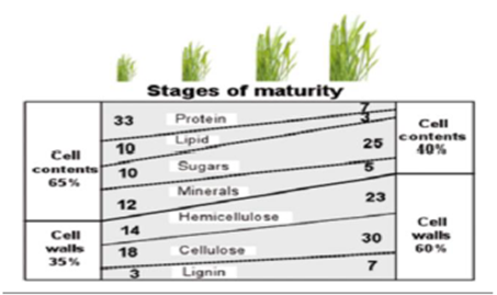
Phase composition of grass with advancing maturity 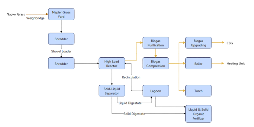
Technological Process Of Biogas Production After Napier grass is harvested in the field using a combine harvester, it is directly chopped and transported to the raw material storage area of the biogas plant. The raw material undergoes processes such as compaction and covering to create silage material, which serves as a beneficial microbial pretreatment. The material is then transported by forklift to the solid feeders, where it is stored and weighed. Subsequently, it is conveyed by a conveyor belt and fed into the digesters through a downward screw conveyor. In the high-load digesters, the substrate undergoes a careful heating process, achieving and maintaining a temperature of ca. +52�?throughout the entire digestion period. Operating under a thermophilic regime, the digester leverages this elevated temperature to drive the necessary biochemical reactions. At regular intervals, mixers are employed to blend the heated substrate within the digester, ensuring thorough mixing and uniformity. The overall processing duration within the digesters averages around 32.8 days (gross). Upon completion of digestion, the substrate is directed to the separator area, where it is effectively separated into solid and liquid digestate. The solid digestate is promptly processed into solid organic fertilizer. Meanwhile, the liquid digestate is carefully directed into a dedicated buffer storage tank for processing liquid organic fertilizer and recirculation. To accommodate the generated biogas, design three Double Membrane Gas Holders, each with effective volume of 3,000 cubic meters. Safeguarding the gasholder against environmental elements, such as precipitation and foreign objects, is a robust weather-resistant film securely fastened using a specialized system. Ensuring operational safety, the digesters are equipped with safety devices to prevent overpressure situations, allowing excess biogas to be safely released into the atmosphere when the pressure reaches above 10 mbar. The biogas produced from HLR is transported by pipelines to the biogas purification system, including processes such as dehydration and desulfurization. These treatment steps aim to remove moisture and sulfides, among other impurities, from the biogas. After the purification treatment, the biogas is directed to the compressor for further processing. Then, the biogas is transported to three points of use—upgrading, boiler, and torch by the booster. The biogas upgrading system adopts PSA technology. Within the upgrading system, biogas is compressed again to 4,000~5,000 mbar and upgraded into natural gas through adsorption agents. The boiler with a capacity of 0.53 MW is installed to provide heating for the HLR. Additionally, the torch is set up in the plant area as a backup device. It can be used to emergency situation, such as equipment failures . All operational processes within the biogas plant are diligently monitored and precisely controlled by an advanced automated system. The central control room, equipped with a central control unit, serves as the operational nerve center. This unit empowers operators to seamlessly switch between automatic and manual modes. Napier Grass Biogas Potential Substrate | Napier Grass | Process Water | Total | Daily Input (t/d) | 290.00 | 170.00 | 460.00 | TS (%) | 20.4 | 5.81 | - | VS/TS (%) | 90.57 | 0 | - | Gas Yield Rate (m3/t VS) | 580.00 | 0 | - | CH4(%) | 52% | 0 | 52% | Daily Biogas Yield (m3/d) | 31,000.00 | 0 | 31,000.00 | Annual Biogas Yield (m3/a) | 10,850,000.00 | 0 | 10,850,000.00 |
The content of impurities in raw materials (soil, sand, iron, etc.) shall not exceed 3% of the total weight. The material is only Napier grass, requiring additional nitrogen sources (such as urea) and trace elements to be supplemented. The annual operating time is calculated based on 350 days. Biogas Plant Characteristics Characteristics | Figure | Unit | Number of Reactors | 3 | sets | Each Total Volume (Gross) | 5,557 | m3 | Each Eff. Volume (Gross) | 5,027 | m3 | Fermentation Temperature | +52 | �?/span> | Organic Load (Primary Fermentation Reactor) | 5.33 | kgODM/ m3 | Retention Time (gross) | 32.79 | days | Volumetric Gas Production Rate | 2.06 | m3/m3.d | Fermentation Concentration | 11.48 | % |
Digestate Outlet L/S Separation | Figure | Unit | TS% In Solid Part After Separation | 25.00 | % | Solid Digestate | 46.67 | t/d | Liquid Digestate | 200.85 | t/d |
Upgrading System Upgrading System | Figure | Unit | Daily Biogas Yield | 30,000.00 | m3/d | Upgrading To CBG | 12 | TPD |
Remark: Calculation Basis: Methane recovery rate 95%, Methane density 0.717kg/Nm3, Carbon dioxide density 1.977kg/Nm³.All the calculations above are estimations and should be considered as reference values only. The actual data may vary and will require adjustments based on factors such as the characteristics of the raw materials during operation and the specific operational conditions.
Main Equipment
Solid Feeder 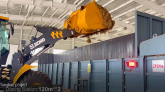
The solid feeder is a device used in a biogas project to accurately measure and evenly distribute straw feedstock before it enters the anaerobic digestion tank. Its primary function is to facilitate the controlled feeding of straw into the fermentation process. This helps optimize biogas production and maintain stable fermentation conditions. The solid feeder works as follows: Weighing and Metering: The solid feeder is equipped with weighing systems to measure the exact amount of straw being fed into the system. This ensures precise dosing and accurate tracking of the feedstock input. Material Handling: The straw is loaded into the solid feeder, where it is stored and prepared for the feeding process. Controlled Discharge: The solid feeder is designed to release the straw in a controlled and regulated manner. This allows for a consistent and uniform distribution of the feedstock, ensuring optimal conditions for the anaerobic fermentation process. Integration with Conveying Systems: The solid feeder is typically connected to conveying systems such as belt, which transport the straw from the solid feeder to the HLR. Monitoring and Control: The solid feeder may be equipped with sensors and automation systems to monitor the feeding process and ensure that the desired feeding rate and quantity are maintained. Specifications Quantity: 2: sets Length: 9.35m Height: 3.46m Width: 4.15m Volume: 40m³
HLR 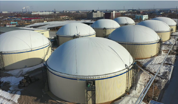
The HLR (High Load Reactor) is a highly effective biogas reactor that offers several advantages when it comes to handling fibrous materials such as Napier grass and other similar feedstocks. HLR has the following advantages. 1) The High Loading Reactor (HLR) can withstand higher material concentrations, adjusting material concentration to achieve a solid content of 12-15%, minimizing the use of added water and reducing the production of liquid digestate. 2) With higher fermentation concentration inside the tank, it fully utilizes the internal friction between fiber materials to enhance mixing efficiency. 3) The HLR can withstand high organic loads; HLR material organic loading rate: 4~9 kg VS/m³·d. Inside the digester, there are heating coils installed. The heating coils ensure efficient and controlled heat transfer within the digester, maintaining optimal temperature conditions for the anaerobic digestion process. The exterior of the digester is insulated with a 100mm thick extruded polystyrene board, providing insulation and thermal protection. The insulation provided by the polystyrene board minimizes heat loss and helps to maintain a stable internal temperature, improving the overall energy efficiency of the system. The insulation layer is further protected and aesthetically enhanced by an outer layer of colored steel plate. Specifications Quantity: 3 sets Diameter: 29.03m Height: 8.4m Each Eff. Volume(Gross) : 5,027.79m³ Platform Of Each Digester: 1 set Spiral Ladder Of Each Digester: 1 set Man Hole Of Each Digester: 1 set Inspection Window Of Each Digester: 2 sets
GFS Tank 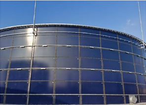
Here are some advantages of using GFS (Glass Fused to Steel) tanks in biogas projects. Corrosion Resistance GFS tanks are highly resistant to corrosion due to the glass-fused coating. They can withstand exposure to hydrogen sulfide, acidic substances, and other corrosive elements present in biogas. This ensures long-term durability and prevents damage to the tank. High Strength and Durability GFS tanks combine the strength of steel with the durability of the glass-fused coating. They can withstand high pressures and heavy loads associated with biogas projects. The tanks have excellent impact resistance and vibration tolerance, making them suitable for various operating conditions. Easy Installation and Maintenance GFS tanks are typically supplied as prefabricated, bolted panels, which makes their installation quick and straightforward. They require minimal maintenance due to the smooth and non-porous glass coating, reducing downtime and operational costs. Versatile Design Options GFS tanks offer flexibility in design, allowing customization based on project requirements. They can be designed in various sizes and configurations to accommodate different volumes of biogas production. Long Service Life GFS tanks have a long service life, thanks to the combination of steel's structural strength and the corrosion resistance of the glassfused coating. They provide reliable storage and containment for biogas over an extended period.
Paddle Agitator 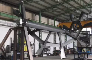
The paddle agitator exhibits the following characteristics suitable for agitating the Napier grass substrate in an anaerobic digester. Long-Shaft agitator For long-shaft agitator, where the stirring shaft extends to the center of the tank, the mixing uniformity and central area blending effectiveness are better ensured compared to side-entry agitators, submersible agitators, and short-shaft agitators. Slow rotation speed A slow rotation speed provides gentle agitation, making it more microbes-friendly, which is beneficial to the collaboration and mass transfer effect between microorganisms. Suitable for High-concentration Materials The mixer is designed to handle materials with high solids content, making it wellsuited for Napier grass with dry matter content up to 15%. Breaking Floating Layer The agitator effectively breaks floating layer that may form on the surface of the digester, ensuring thorough mixing and preventing the formation of scum or crust. Stirred And Mixed Thoroughly Thorough stirring of the materials in the HLR helps ensure uniform mixing during the fermentation process. This ensures efficient decomposition of organic matter and optimum gas yield. Suitable for Primary & Post Digester The agitator is suitable for use in both primary and post-digesters, accommodating different stages of the anaerobic digestion process. Maintenance-Friendly Design The agitator features a container bearing made of special, highly wear-resistant, and maintenance-free materials. This allows for easy replacement of components without the need to drain the digester or replace the agitator shaft. Strong Adaptability Of Raw Material Fluctuation This type of agitator is effective for fluctuations in raw material concentration and feed volume, ensuring that effective mixing can be maintained under fluctuating raw material conditions. Specifications-Primary HLR Quantity: 4 sets Power Capacity: 22kW Quantity: 4 sets Power Capacity: 18.5kW Specifications-Secondary HLR Quantity: 2 sets Power Capacity: 15kW Quantity: 2 sets Power Capacity: 11kW
Double Membrane Gas Holder 
Integrated double-membrane gas holders are designed to efficiently store and manage the produced biogas. Here are the key features and advantages of the integrated double membrane biogas holders. Advanced technology The holders utilize a double-membrane design, consisting of an inner membrane and an outer membrane. This design ensures maximum gas tightness, preventing any gas leakage. High-quality materials The membranes used are made of top-grade materials imported from reputable suppliers. They are chemically resistant to biogas components and provide excellent permeability resistance to methane. The outer membrane is specially coated to enhance UV radiation resistance, ensuring long-term durability. Reliable performance The integrated design of the gas holder ensures safe and stable operation. The double-membrane structure provides added protection against environmental factors and potential damage. Flexibility and scalability These gas holders can be customized to meet specific project requirements in terms of capacity and dimensions. The modular design allows for easy expansion or reduction of storage capacity as the biogas production fluctuates over time. Efficient space utilization The compact design of the gas holder optimizes the utilization of available space, whether on the tank or on the ground. This is particularly beneficial for projects with limited land availability. Cost-effective The use of integrated double-membrane biogas holder offers cost savings compared to traditional storage solutions. They require lower installation and maintenance costs, contributing to overall project affordability. Specifications Double Membrane Gas Holder Quantity: 3 sets Diameter: 29.03m Height: 8.7m Eff. Volume: 3,000m³ Safty Device Of Each Gas Holder: 1 set Air Blower Of Each Gas Holder: 2 sets
Screw Pump 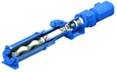
The screw pump offers practicality and distinctive features when it comes to handling fibrous materials like Napier grass. Here are its advantages: Efficient handling of fibrous materials The screw pump is specifically designed to handle high-fiber content materials. Its unique screw structure and pump chamber allow for effective transportation of fibrous materials to subsequent processing equipment, ensuring a continuous and efficient process flow. High wear and corrosion resistance The pump chamber and screws of the screw pump are constructed from durable materials that offer excellent resistance to wear and corrosion. This ensures reliable and long-lasting performance even when handling abrasive fibrous materials. Gentle product handling The gentle pumping action of the screw pump minimizes the degradation of fibrous materials during the pumping process. This helps to preserve the integrity of the fibers and maintain the quality of the material being transported. Versatile application range The screw pump is suitable for a wide range of applications, including the handling of fibrous materials like Napier grass. It can be seamlessly integrated into various biogas plant processes, providing efficient and reliable pumping solutions. Easy maintenance and servicing The design of the screw pump allows for easy access to components, facilitating maintenance and servicing tasks. This helps to minimize downtime and ensure smooth operation of the pumping system. Specifications Quantity: 3 sets Flow Rate(Gross): 60-80m³/h Power Capacity: 18.5kW
Solid-Liquid Separator 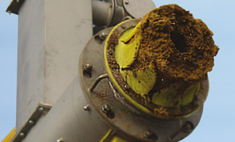
Screw Press Separator is specifically designed for solid-liquid separation in biogas projects utilizing fermentation materials such as corn straw and Napier grass. This separator effectively separates the liquid phase from the solid phase, allowing for efficient management of the materials. With its durable construction and self-cleaning screen basket, it ensures reliable operation and requires minimal maintenance. The separator enables high dry matter content in the separated solids and offers flexible options for managing the separated liquid. The liquid portion can be recycled back into the system or stored for future use as organic fertilizer in surrounding agricultural fields. The separated solid fraction, known as digestate, is stored in a dedicated storage area and can be utilized as nutrient-rich fertilizer by returning it to the fields. Specifications Quantity 3 sets Flow Rate(Gross) 10-15m³/h Power Capacity 7.5kW
Desulfurization 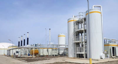
Oxidation iron desulfurization is suitable for desulfurization of biogas produced from fibrous substrate as a feedstock. It operates based on the following desulfurization principle: During the desulfurization process, the hydrogen sulfide (H2S) present in the biogas reacts with the oxidation iron (Fe2O3) to form iron sulfide (FeS) and water (H2O). The iron sulfide is then further oxidized to form elemental sulfur (S) and iron oxide (Fe2O3). This reaction helps to remove H2S from the biogas, reducing its concentration and minimizing its harmful effects. The advantages of oxidation iron desulfurization for Napier Grass biogas are as follows: High Desulfurization Efficiency Oxidation iron desulfurization has a high removal efficiency for H2S, effectively reducing its concentration in the biogas. Cost-Effective The use of oxidation iron as a desulfurization agent is relatively inexpensive compared to other desulfurization methods, making it a cost-effective choice. Safety The desulfurization process using oxidation iron is considered safe, as it does not require the use of toxic or hazardous chemicals. Simple Operation The desulfurization system employing oxidation iron is easy to operate, with straightforward procedures and minimal maintenance requirements. Environmental Compatibility The desulfurization process results in the conversion of H2S into elemental sulfur, which can be collected and utilized as a valuable resource or safely disposed of in an environmentally friendly manner. Specifications Quantity of Tower 2 sets Size φ1.5×7m (H) Material of Tower Carbon Steel Biogas Upgrading System: 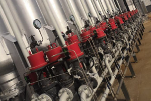
The principle of the Membrane Separation System is primarily based on the use of semipermeable membranes to selectively separate mixtures. Here are several key points regarding the working principle of membrane separation systems: Selective Barrier: The membrane acts as a selective barrier that allows certain components to pass through while retaining others in the liquid or gas mixture. Pressure-Driven Membrane Separation: This type of membrane separation is driven by positive and negative pressure, causing solvents and solutes to pass through the micropores or pores of the membrane. Common methods include Reverse Osmosis (RO), Nanofiltration (NF), and Ultrafiltration (UF). Sieving Effect and Charge Effect: Nanofiltration membrane separation has a sieving effect and a charge effect (Donnan effect), meaning that charged groups on the membrane surface or within the membrane affect the separation behavior of inorganic salts. Membrane Materials and Structure: The effectiveness of membrane separation largely depends on the structure and properties of the membrane, including the pore structure and chemical composition. Driving Forces: Membrane separation processes can be driven by various forces, including pressure gradients, concentration gradients, and electric fields. Efficiency and Energy Saving: Compared to traditional separation processes, membrane separation processes are usually more efficient and energy-saving because they are mainly driven by pressure gradients or concentration gradients, rather than relying on thermal energy.
Equipment List No | Unit | Equipment | Characteristic | Quantity | 1 | Feedstock Transport and Storage Unit | Shovel Loader | Bucket Volume: 4m3 | 3 | 2 | Weighbridge | Weighing Range: 0-80t, Size: 3.0x18.0m, Carbon Steel. | 1 | 3 | Shredder | Particle Size�?/span>3cm,Capacity: 15 t/h, Including Conveyor Belt | 2 | 4 | Feeding Unit | Solid Feeder | Open Container with Weighing Display; Size�?/span> 9.35×4.15×3.46m (H), Material: Carbon Steel; Volume=40 m3; P:7.5KW×3+1.1KW×1; 6 Weighing Sensors; 1 Display, | 2 | 5 |
| Conveyor Belt | Capacity: 15t/h; Width: 1,000mm; Including Windproof Cover. | 2 | 6 |
| Screw Conveyor | Capacity�?/span> 15t/h, Screw Diameter: 400mm; Material of Screw: SS304; P:7.5kW×1,ExdIIBT4 | 2 | 7 | Anaerobic Digestion Unit | High Load Reactor | GFS Tank, Size: φ29.03×8.4m (H); Including�?/span> Enamelled Steels: 9mm 38 pcs�?/span> 8mm 38 pcs, 7mm 38 pcs, 6mm 152 pcs;Size:1.2×2.4m; Platform Size: W=800mm,L=2.5m,1pc; Ladder Size: W=650mm.L=11.8m,1pc; Excluding Lightning Rod. | 3 | 8 | Observation Window | Observation Window size:DN300,2 pcs | 6 | 9 | Positive and Negative Pressure Protector | Positive and Negative Pressure Protector:+1000Pa~-300Pa | 3 | 10 | High Load Reactor Insulation | Extruded polystyrene Board (100mm), Insulation Covering According to Owner's Requirements | 3 | 11 | Heating Coil | Primary HLR Carbon Steel,DN50,Length: 200m | 2 | 12 | Heating Coil | Secondary HLR Carbon Steel,DN50,Length: 100m | 1 | 13 | Jacking System | Tools for installing GFS Tank Outrigger and Electric Hoist: 40pcs. Distribution Box: 1pc. | 1 | 14 | Paddle Agitator | Primary HLR, Including Support Bracket, Carbon Steel. Blades: L=3,500mm.Carbon Steel. Shaft: L=14,050mm,Carbon Steel. P:22 KW,ExdIIBT4. | 4 | 15 | Paddle Agitator | Primary HLR, Including Support bracket, Carbon Steel. Blades: L=3,500mm.Carbon Steel. Shaft: L=11,600mm.Carbon Steel. P:18.5kW, ExdIIBT4. | 4 | 16 | Paddle Agitator | Secondary HLR, Including Support Bracket, Carbon Steel. Blades: L=3,500mm,Carbon Steel. Shaft: L1=14,050mm,Carbon Steel. P:15kW,ExdIIBT4. | 2 | 17 | Paddle Agitator | Secondary HLR, Including Support Bracket, Carbon Steel. Blades: L=3,500mm,Carbon Steel. Shaft: L2=11,600mm,Carbon Steel. P:11kW,ExdIIBT4. | 2 | 18 | Double Membrane Gas Holder | Gas Holder on the Tank Roof; Size: φ29.03x8.7m (H), Capacity: 3,000 m3, Material of Membrane: Polyester Fiber Membrane. Fan:2 pcs; P:1.5KWx2,ExdIIBT4. Material of Fan: fiberglass. | 3 | 19 | Emergency Generator | Diesel, P:200 KW, Voltage: 415V | 1 | 20 | Pump Unit | Screw Pump | Flow Rate: 60-80 m3/h, Pressure:2bar, Inlet Flange:DN150,10bar, Outlet Flange:DN150,10bar, P:18.5kW, Material of Stator: Nitrile Butadiene Rubber Material of Rotor: Cr12MoV | 3 | 21 | Air Compressor System | For Valves Vperation,0.67m3/min, 0.8MPa, Including: Air Compressor, Dryer, Air Storage Tank, Filter. | 1 | 22 | Solid-Liquid Separation Unit | Solid-Liquid Separator | Screw Press, P: 7.5kW, Capacity: 10-15 m3/h, Screen Basket Slot Size: 1mm+1mm; Material of Screw : SS304. | 3 | 23 | Membrane- Covered Lagoon Unit | Submersible Mixer(lagoon) | P: 5.0KW, Material: SS304. | 1 | 24 | Submersible Pump(lagoon) | Centrifugal Pump, Q: 100 m3/h, H:15 m,P:15kW. | 2 | 25 | Biogas Compressor (lagoon) | P: 7.5KW, Q=5m3/min, ExdIIBT4, Frequency Conversion | 1 | 26 | Biogas Purification and Compression Unit | Chemical Desulfurization System | Desulfurization Tower Size φ 5x7.0m (H), Quantity: 2 pcs; Material of Tower: Carbon Steel. Inlet:200ppm, Outlet: �?0ppm; Including: Ladder and Initial Loading of Desulfurizer-Fe2O3, Weight of Fe2O3 :7.05t.Sulfur Capacity: 25%. | 1 | 27 | Biogas Chiller | Processing Capacity: 1,300 m3/h, P:32kW,ExdIIBT4. Inlet:55T: Out:15�?/span>; Material: In Contact with Gas Made of Stainless Steel 304. Explosion-proof type, Biogas Dew Point Temperature:15�?/span>. Removal Efficiency: 80% | 1 | 28 | Biogas upgrading system | Biogas Upgrading System | Pre-Compression & Membrane Separation System; Fueling Column*1 set & Fueling Nozzle*1 set; Capacity:30,000m3/d(Biogas) | 1 | 29 | Emergency Release Unit | Torch | Pre-Compression & Torch; Internal Combustion Type, Processing Capacity: 800 m3/h, Carbon Steel | 1 | 30 | Heating Unit | Heating System | Pre-Compression & Boiler System and Hot water circulation; Capacity: 0.53MW | 1 | 31 | Electrical and Control Unit For Biogas System | Electrical and automation system, Distribution System, Software system | Including MCC cabinet, PLC cabinet, Operator Panel, Field Control Cabinet. Distribution Cabinet and Software and programming | 1 | 32 | other components of Distribution System | Cable, Transformer, Lightning protection | 1 | 33 | Automation Control Instrument System | Liquid Level, Temperature, Pressure, Flow Rate. Electromagnetic Flowmeters: 4 pcs; Level transmitters: 7 pcs; Level switches: 1 pc; Temperature sensors: 6 pcs; Methane leak alarms: 4 pcs; Biogas pressure sensors: 6 pcs; Air pressure sensors: 3 pcs; Biogas flowmeters: 3 pcs. | 1 | 34 | Pipeline Unit | Pipeline | Piping and Valves | 1 | 35 | Others equipment Unit | Laboratory Instruments | FOS, TAC, PH, TS, VS, NH4-N, Individual Acids .(Laboratory instruments and chemicals, laboratory benches, chairs, fume hoods) | 1 | 36 | CI Identification Sign | CI Identification Sign (According to Owner's Requirements) | 1 | 37 | Biogas Gas Analyzer | Online Gas Analyzer (Fixed Type) , Two Channels ;CH4, H2S, O2, CO2 | 1 |
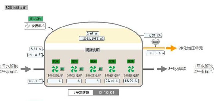 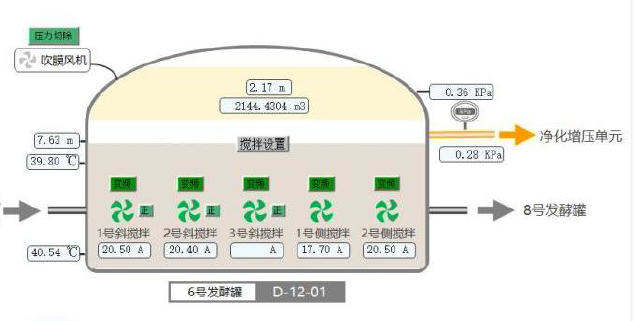
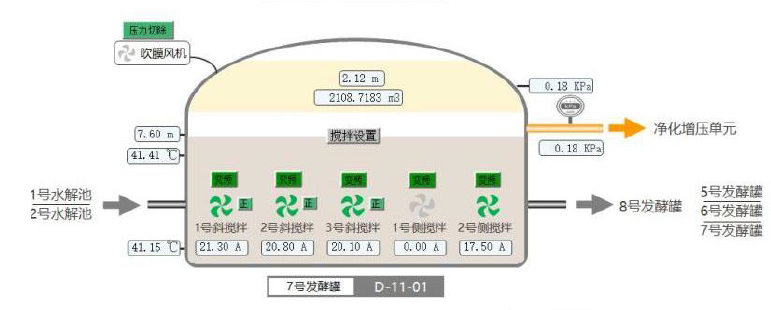 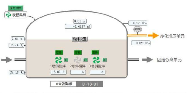
PLC System A Programmable Logic Controller (PLC) is a crucial component in biogas power generation projects. It serves as a control system that monitors and regulates various aspects of the power generation process. The PLC in a CBG project is responsible for performing tasks such as data acquisition, process control, and equipment monitoring. It collects data from sensors and instruments installed throughout the system, including pressure sensors, temperature sensors, flow meters, and level sensors. This data is used to ensure the efficient and safe operation of the CBG plant. The PLC utilizes its programming logic to control and coordinate different functions within the power generation system. It executes predefined instructions and algorithms to manage processes such as biogas flow control, engine startup and shutdown, load balancing, and fault detection. The PLC continuously monitors the system parameters and adjusts the operation accordingly to optimize performance . Additionally, the PLC provides a human-machine interface (HMI) that allows operators to interact with the control system. Through the HMI, operators can access real-time data, configure system settings, and receive alarms and notifications in case of abnormalities or equipment failures. The advantages of using a PLC in CBG projects include enhanced automation, improved system reliability, accurate control of process variables, efficient fault diagnosis, and remote monitoring capabilities. Component | Specification/Brand | PLC | ABB, Siemens, or equivalent brands | Inverter | ABB, Siemens or equivalent brands | Motor | Wanneng, Nanyang, or equivalent brands | Electrical wire | YJV, KVV, KVVP, BV, ASTP-120-2*2*1.5 | Cable tray and support | Hot-dip galvanized bridge, fiberglass bridge | Wiring conduit | Hot dip galvanized steel, PVC | Electrical control panel | ABB, Schneider or equivalent brands | Lighting system | Inside Building & service area are non-explosion proof type | Lightning protection | Surge protection system for instrument. |
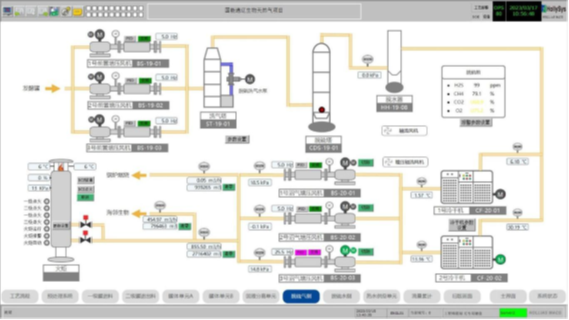
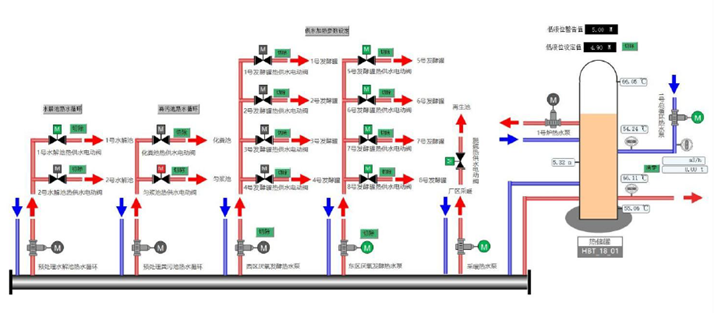
|

