| Annex 1: Integrated Valve Technical Specification I. Technical Specifications 1. Model: ATYF-10 2. Shape: Bottle neck PZ27.8 tapered thread, oxygen-specific oil-free cylinder valve, fully degreased valve body thread fit without slippage or chipped teeth. 3. Product Function: Reduces high-pressure oxygen inside the cylinder (equal to or less than 20 MPa) to an output range of 0.3 to 0.5 MPa. 4. Material: Copper core 5. Gas Type: Oxygen 6. Filling Interface: G5/8 external thread interface with built-in filtration device. 7. Oxygen Outlet: Dual options - 9/16 threaded interface with check valve and barbed outlet nozzle. 8. Flow Adjustment Device: Equipped with mechanical manual flow adjustment device, offering ten adjustable positions in clockwise/counterclockwise direction; Flow range: 0-25 L. 9. Pressure Regulator Range: Inlet interface not exceeding 20 MPa; Outlet interface in the range of 0.3 to 0.5 MPa. 10. Flow Rate: Valve output flow adjustable within maximum 25 +/- 0.1 L/min and minimum 0.5 +/- 0.1 L/min. 11. Pressure Relief Safety Valve: Equipped with safety relief port; automatically relieves pressure when pressure reducing device fails to prevent high-pressure oxygen output from the oxygen outlet. 12. Overpressure Safety Valve: Automatically reduces pressure and vents when pressure exceeds 25 MPa. 13. Pressure Gauge: Pressure gauge must be free from scars, cracks and other defects; internal dial reading must be clear; externally fitted with mechanical glass pressure dial. 14. Cylinder Requirements: Bottle neck thread PZ27.8 oxygen-specific tapered thread; cylinder design working pressure must not be lower than 15 MPa; bottle neck free from cracks, deformation, or severe corrosion; oxygen-specific oil-free cylinder valve with fully degreased valve body, thread fit without slippage or chipped teeth. 2) Valve hydrostatic test: 250 bar, 180 bar hold for 1 min, zero leakage, smooth opening and closing. 3) Valve port compatible with general industrial oxygen pressure regulators in Nigeria, accompanied by valve factory certificate and degreasing inspection report. 4) Strictly prohibited to mix with nitrogen / flammable gas cylinder valves. 15. Filling Temperature: Ambient 15-38 degrees C optimal for filling; >42 degrees C prohibited for filling; damage caused by high-temperature overfill exceeding pressure is not covered by warranty. 16. Operating Temperature: Integrated valve normal operation: -10 degrees C to +50 degrees C; Short-term storage and transport limit: -15 degrees C to +55 degrees C (container sea freight); >55 degrees C environment prohibits pressurized storage. Damage caused by exceeding temperature limits is not covered by product warranty. 17. Storage Constraints: During rainy season, do not submerge in standing water for extended periods (water depth >500 mm, soaking >72 h exceeds agreed usage conditions); During dry season, outdoor storage requires sun protection (continuous exposure >50 degrees C prohibited). 18. Labeling: Laser or screen printing, content subject to contract requirements. 19. This product is for export to Jigawa State, Nigeria. Annex 2: User Manual I. Basic Product Information Please inspect the gas cylinder according to the gas supplier's instructions. Be sure to remove any debris from the cylinder valve seat. Check the pressure regulator for oil or grease contamination. If found, do not use. Gently screw the large nut on the pressure regulator onto the cylinder valve interface. Tighten the nut with a wrench until secure. Connect the oxygen supply tube to the pressure regulator outlet. I. Operating Instructions Ensure the pressure regulator is in the "OFF" position by rotating the knob counterclockwise to the "0" position. For safety, when opening the cylinder valve, do not face or stand with your back to the pressure regulator. Slowly open the cylinder valve counterclockwise approximately one full turn. If a hissing sound is heard, the system has a leak. Close the cylinder, open the pressure regulator to release accumulated pressure. Try tightening the regulator onto the cylinder, then open the cylinder again. If the problem persists, close the system again and contact your service representative. Never attempt to repair the pressure regulator or cylinder yourself. Turn the knob clockwise to adjust the flow setting until the window displays the desired setting value. If cylinder pressure drops below 300 PSI, replace with a full cylinder. Close the system, close the cylinder valve, wait for oxygen/nitrogen to flow out from the pressure regulator, then turn the regulator to the "0" position. Never attempt to remove the pressure regulator unless the cylinder is closed and pressure has been released. Product Specifications Table: No. | Item | Technical Specifications | 1 | Gas Medium | Oxygen / Nitrogen | 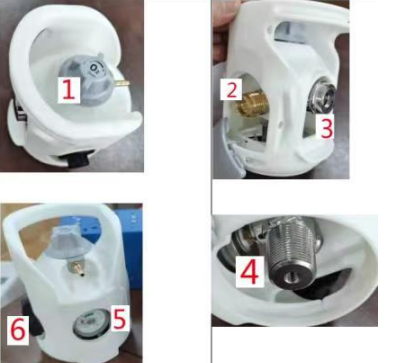
| 2 | Product Structure | 1.Flow Rate: 0-25Lpm |
|
| 2.Inflatable Port: G5/8 Male Thread |
|
| 3.Air Outlet: 1 barb + 1 CV (Check Valve) |
|
| 4.Cylinder Thread: PZ27.8 |
|
| 5.Pressure Gauge: 0-20MPA |
|
| 6.On/Off Switch: For gas flow control | 3 | Input Pressure | 15-20 MPa |
| Output Pressure | 0.3-0.45 MPa |
II. Precautions1. The designed service life of the integrated valve is at least one regular inspection cycle of the steel cylinder (usually 3 years). The actual service life must be evaluated through regular inspection synchronized with the cylinder.2. The rated working load of the plastic handle generally does not exceed 30 kg.3. Safety Precautions During UsePre-installation and Pre-use Inspection- Media Compatibility Verification: Confirm that the valve body material is compatible with the gas medium (such as oxygen, hydrogen, corrosive gases) to avoid stress corrosion cracking or material embrittlement.- Appearance and Leak Inspection: Check the valve body for cracks, deformation, or corrosion; detect all interfaces with soapy water or helium leak detector. Strictly prohibited to us e with leaks.- Operating Mechanism Inspection: Confirm that the valve opens and closes smoothly without sticking or slipping; pressure relief devices, flow limiters and other safety accessories are intact and effective.III. Operational Safety Standards- Slow Opening and Closing, Avoid Impact: When opening the valve, stand sideways away from the outlet direction and open slowly to prevent high-pressure gas flow impact from damaging seals or causing pressure gauge malfunction. - Strictly Prohibit Overpressure / Over temperature Use: System pressure must not exceed 1.1 times the rated working pressure; ambient temperature must be within the allowable range of the valve components, avoid open flame baking or low-temperature freezing (e.g., CO2, N2 and other gas decompression absorbs heat and easily freezes). - Prohibit Pressurized Disassembly: Before maintenance or valve replacement, the cylinder main valve must be closed first, residual gas in the pipeline must be vented and pressure confirmed to be zero before operation. - Special Gas Prohibitions: Oxygen integrated valves must strictly avoid contact with grease or oil to prevent combustion or explosion; flammable gas valves must be kept away from fire sources and maintain good ventilation. IV. Regular Maintenance and Inspection- Synchronized Inspection with Cylinder: The integrated valve must undergo regular inspection every 3 years synchronized with the cylinder, focusing on gas tightness, pressure relief device performance, and valve body corrosion. - Routine Maintenance Points: - Regularly clean the valve surface to prevent dust and impurities from entering the sealing surface; - Check valve stem seals and threads for aging or wear, replace if necessary; - For valves with pressure relief devices, regularly verify that the relief pressure is within the specified range. - Abnormal Condition Handling: If valve leakage, switch failure, or pressure relief device abnormality is found, immediately stop using the cylinder, contact professional personnel for repair, and strictly prohibit unauthorized disassembly or repair. - In case of flammable / toxic gas leakage, immediately shut off the gas source, evacuate personnel, activate the ventilation system, and strictly prohibit switching electrical equipment or using open flames; - In case of fire, if the cylinder is in the fire scene, priority should be given to cooling the cylinder body, handled by professional personnel, and strictly prohibit unauthorized approach or operation.
|




 Buyer
Buyer Inquiry Basket
 Supplier
 Register